Liquid crystal panel, liquid crystal display device, television device, and method of manufacturing liquid crystal panel

Inactive Publication Date: 2013-09-12
SHARP KK
View PDF3 Cites 3 Cited by
  • Summary
  • Abstract
  • Description
  • Claims
  • Application Information

AI Technical Summary

Benefits of technology

[0038]According to the technology disclosed herein, a liquid crystal panel in which a bright point defect is cor

Problems solved by technology

The bright point defect extremely degrades the displ

Method used


Image

  • Liquid crystal panel, liquid crystal display device, television device, and method of manufacturing liquid crystal panel
  • Liquid crystal panel, liquid crystal display device, television device, and method of manufacturing liquid crystal panel
  • Liquid crystal panel, liquid crystal display device, television device, and method of manufacturing liquid crystal panel

Examples


Example

[0059]A first embodiment will be described with reference to the drawings. An X-axis, a Y-axis, and a Z-axis are illustrated in a part of each drawing. Directions indicated by the axes in each drawing correspond to directions indicated by the respective axes in other drawings. A Y-axis direction corresponds to a vertical direction and an X-axis direction corresponds to a horizontal direction.

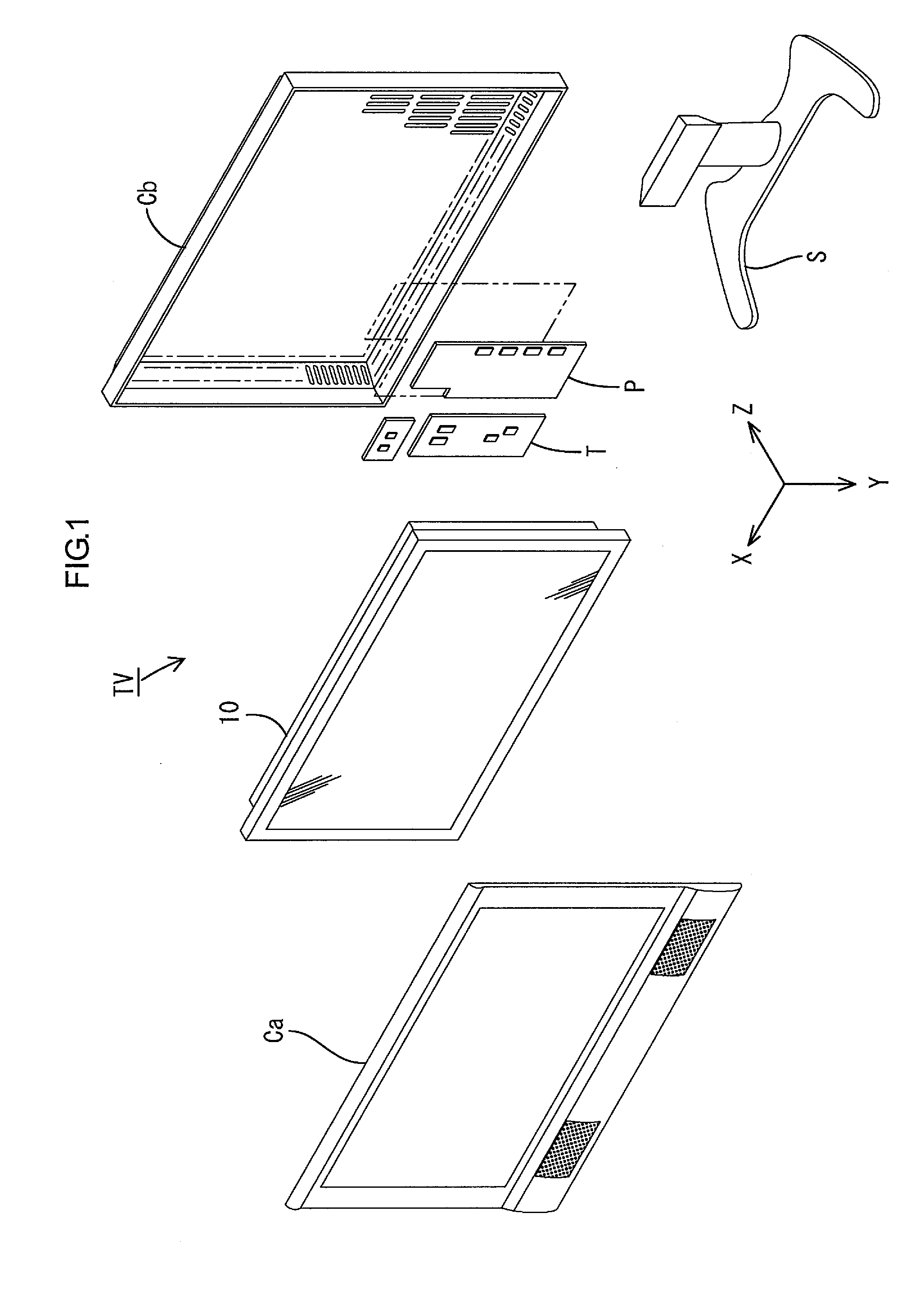
[0060]FIG. 1 illustrates a television device TV according to the first embodiment in an exploded perspective view. As illustrated in FIG. 1, the television device TV includes a liquid crystal display 10, front and back cabinets Ca and Cb which house the liquid crystal display device 10 therebetween, a power supply P, a tuner T, and a stand S. The liquid crystal display device 10 has a landscape rectangular shape as a whole and held in the vertical position.

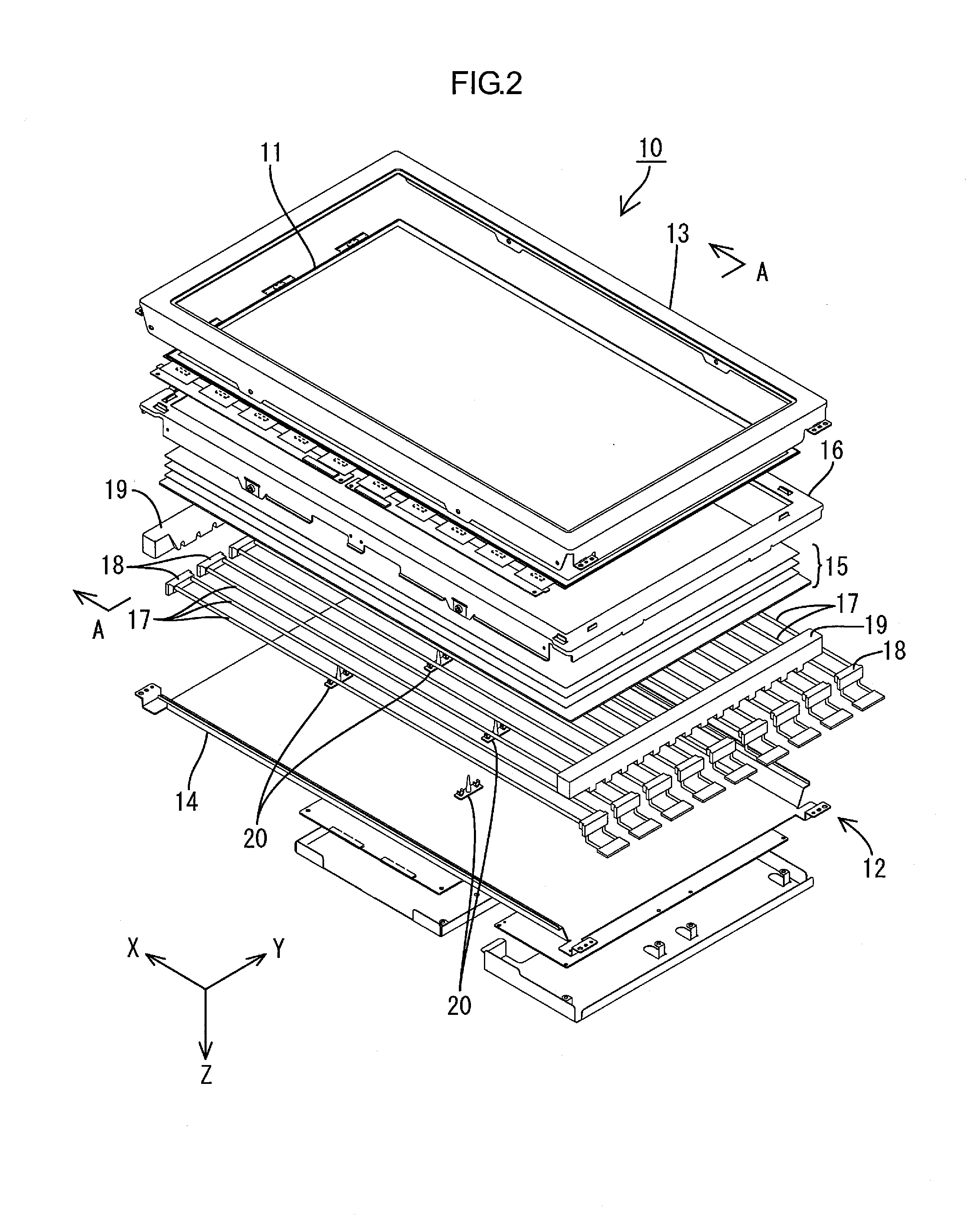
[0061]FIG. 2 illustrates the liquid crystal display device 10 in an exploded perspective view. FIG. 3 illustrates the liquid crystal display ...

Example

Second Embodiment

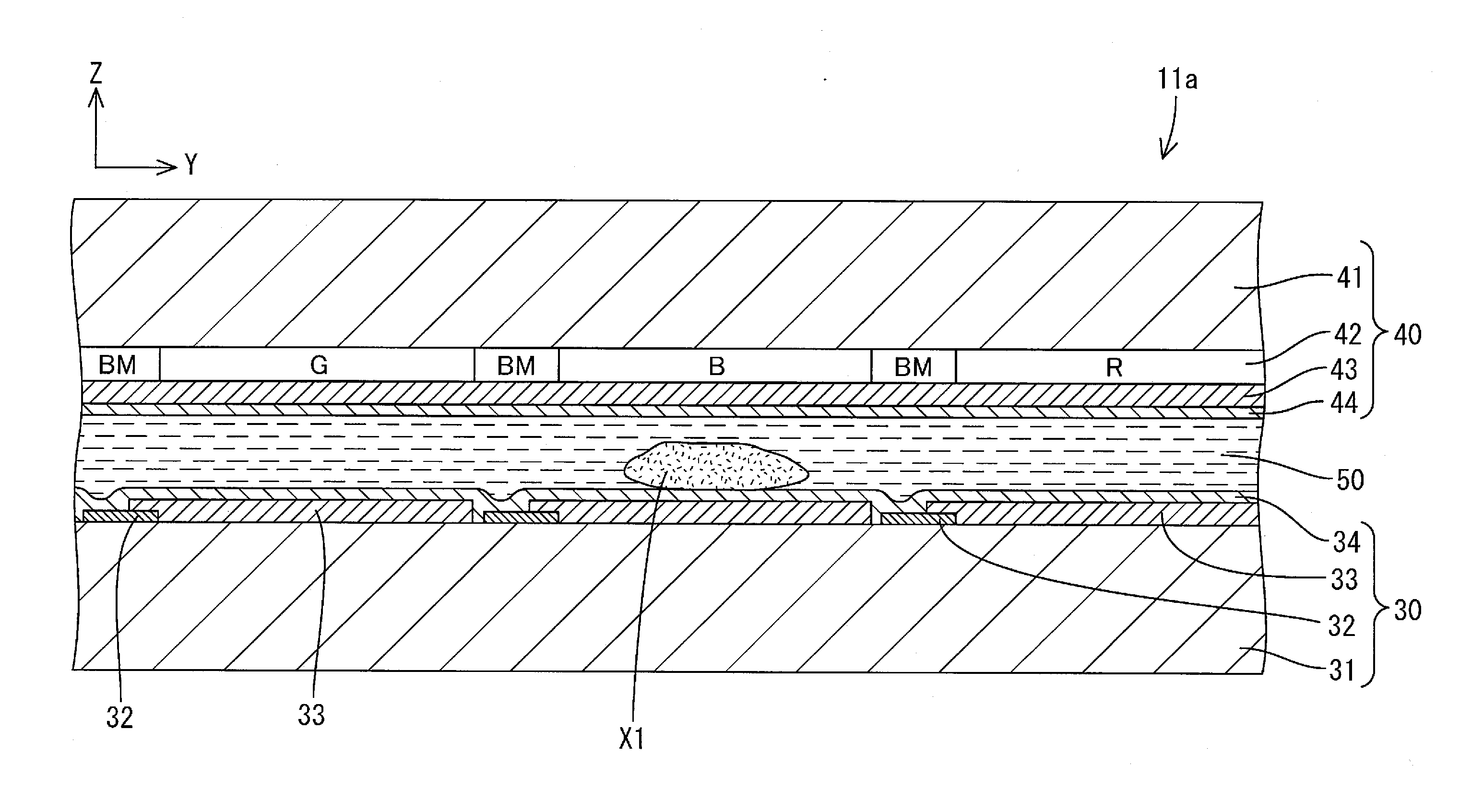
[0092]A second embodiment will be described with reference to the drawings. FIG. 14 is a cross-sectional view illustrating a portion of a glass substrate 141 provided on the front side (light exit side) of the liquid crystal panel and a portion of a color filter 142, and the portions are adjacent to the colored section B to be corrected. FIG. 15 is a plan view of a portion of the color filter 142 adjacent to the colored section B to be corrected seen from the front. The second embodiment differs from the first embodiment in the method of blackening a part of the color filter 142 in the light blocking portion forming process. Other structures are same as those of the first embodiment, and thus configurations, functions, and effects similar to those of the first embodiment will not be explained. In FIG. 14 and FIG. 15, portions indicated by the number obtained by adding 100 to the reference numerals in FIG. 8 and FIG. 9 are same as the portions explained in the first ...

Example

Third Embodiment

[0094]A third embodiment will be described with reference to the drawings. FIG. 16 is a magnified cross-sectional view of a liquid crystal panel 211 according to the third embodiment. The second embodiment differs from the first embodiment in the position of the second light blocking portion BL2. Other structures are same as those of the first embodiment, and thus configurations, functions, and effects similar to those of the first embodiment will not be explained. In FIG. 16, portions indicated by the number obtained by adding 200 to the reference numerals in FIG. 13 are same as the portions explained in the first embodiment.

[0095]In the liquid crystal panel 211 according to the third embodiment, the second light blocking portion BL2 is formed in the glass substrate 41 that is on the rear side. The second light blocking portion BL2 is formed in a portion of the glass substrate 41 that overlaps the foreign obstacle X1 and on a surface of the glass substrate 41 that i...


PUM


Abstract

A method of manufacturing a liquid crystal panel in which the bright point defect is effectively corrected is provided. The method of manufacturing a liquid crystal panel 11 including a pair of substrates 40 and 30, and a liquid crystal layer 50 provided between the pair of the substrates 40 and 30 includes detecting a bright point defect in the liquid crystal panel 11; forming a first light blocking portion BL1 in one of the substrates 40 and 30 and in a part of an area that surrounds the bright point defect with a plan view; forming a recess in a portion of one of the substrates 40, 30 that overlaps the bright point defect and on a surface of the one of the substrates 40 and 30 that is opposite from a surface facing the liquid crystal layer; and forming a second light blocking portion BL2 in the recess.

Description

TECHNICAL FIELD[0001]The present invention relates to a liquid crystal panel, a liquid crystal display device, and a television device, and a method of manufacturing a liquid crystal panel.BACKGROUND ART[0002]One of known methods of manufacturing a liquid crystal panel is described below. Switching components (e.g., TFTs) and pixel electrodes are arranged on one of a pair of glass substrates. Counter electrodes are arranged on the other one of the pair of glass substrates. Thereafter, the pair of glass substrates is bonded together with a spacer therebetween. Liquid crystals are injected between the glass substrates to form a liquid crystal layer. Then, polarizing plates are attached to respective outer surfaces of the glass substrates to obtain a liquid crystal panel.[0003]Such a manufacturing process of a liquid crystal panel may include a test process that is executed at a predetermined timing for detecting errors. For example, the test process may be executed after the liquid cr...

Claims


Application Information

Patent Timeline
IPC IPC(8): G02F1/1335
CPCG02F1/1333G02F2201/508G02F2001/133368G02F1/133512G02F1/133368
Inventor TANAKA, SHIGEKITOMIMARU, NOBUFUMIKANBE, MAKOTOTAKEUCHI, SHUNICHIOKETANI, TAIMI
Owner SHARP KK
Why Eureka
Try Eureka