Thin-film transistor array and method for manufacturing same

a technology of thin-film transistors and transistor arrays, applied in transistors, optics, instruments, etc., can solve problems such as likely shortening, and achieve the effects of reducing production losses, improving yield and product quality, and increasing parasitic capacitan

Inactive Publication Date: 2003-12-02
NEC LCD TECH CORP
View PDF8 Cites 1 Cited by
  • Summary
  • Abstract
  • Description
  • Claims
  • Application Information

AI Technical Summary

Benefits of technology

are summarized as follows, but not limiting thereto.According to the present invention, as described above, the following meritorious effects may be achieved:(1) According to the present invention, since the gate insulating lying below the pixel electrode in roughly its entirety or a slit-like area thereof extending along the drain bus line is removed simultaneously during the step of etching the contact hole, it becomes possible to remove the residual a-Si produced due to patterning defects during the island-forming step. Thus, with the present invention, the point defects of semi-bright spots, otherwise produced by interconnection to the drain bus line and resulting capacitative coupling to the pixel electrode, can be suppressed, thereby reducing the reject ratio to improve product yield.(2) Also, according to the methods of the present invention, since the entire gate insulating film below the gate electrode of the gate insulating film or a slit-like area of the gate insulating film along the drain bus line is etched off by the same patterning step as that used for providing the through-hole serving for interconnecting the metal film forming the gate electrode and the metal film forming the drain and source electrodes and the drain bus line, the number of the patterning steps is the same as that required in the conventional process, thus evading complication of the manufacturing process.(3) Moreover, according to the present invention, since there is the passivation film as an insulating / boundary separating film extending between the drain bus line and the pixel electrode, such a structure is obtained in which point defects such as bright and dark spots ascribable to the shorting between the drain bus line and the pixel elect rode can be reduced. Further, since the drain bus line and the pixel electrode are provided in different layers, the pixel electrodes can be increased in area thus simultaneously increasing the opening area.Various aspects, embodiments and any features or elements thereof may be combined together according to the gist of the present invention. Also it should be noted any modifications may be introduced within the gist and scope of the present invention herein disclosed and claimed as appended.

Problems solved by technology

However, if residual patterning troubles would occur in any patterning process, shorting is likely to occur between the drain bus line 112 and the pixel electrode 106.

Method used


Image

  • Thin-film transistor array and method for manufacturing same
  • Thin-film transistor array and method for manufacturing same
  • Thin-film transistor array and method for manufacturing same

Examples


embodiment 1

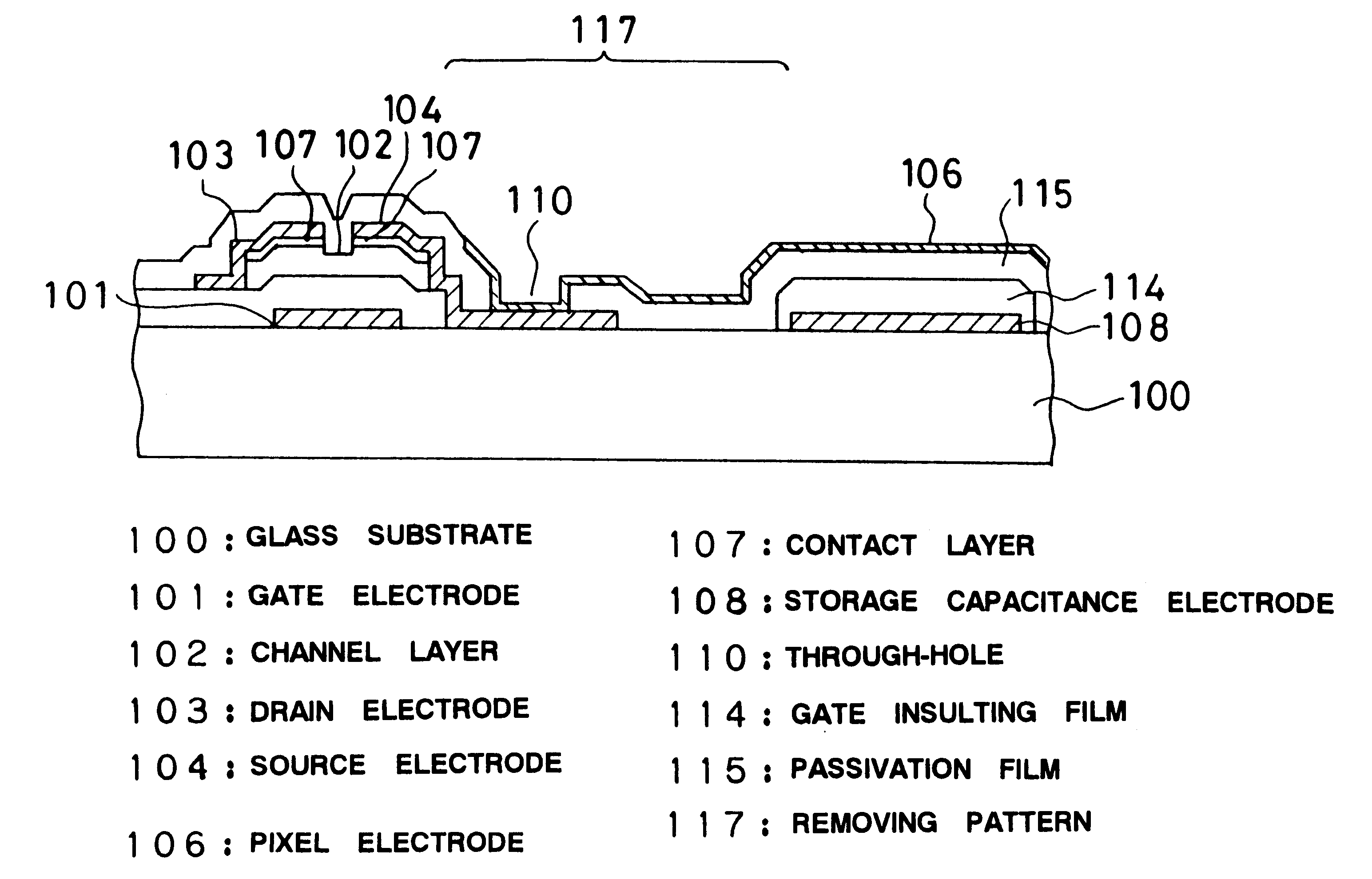
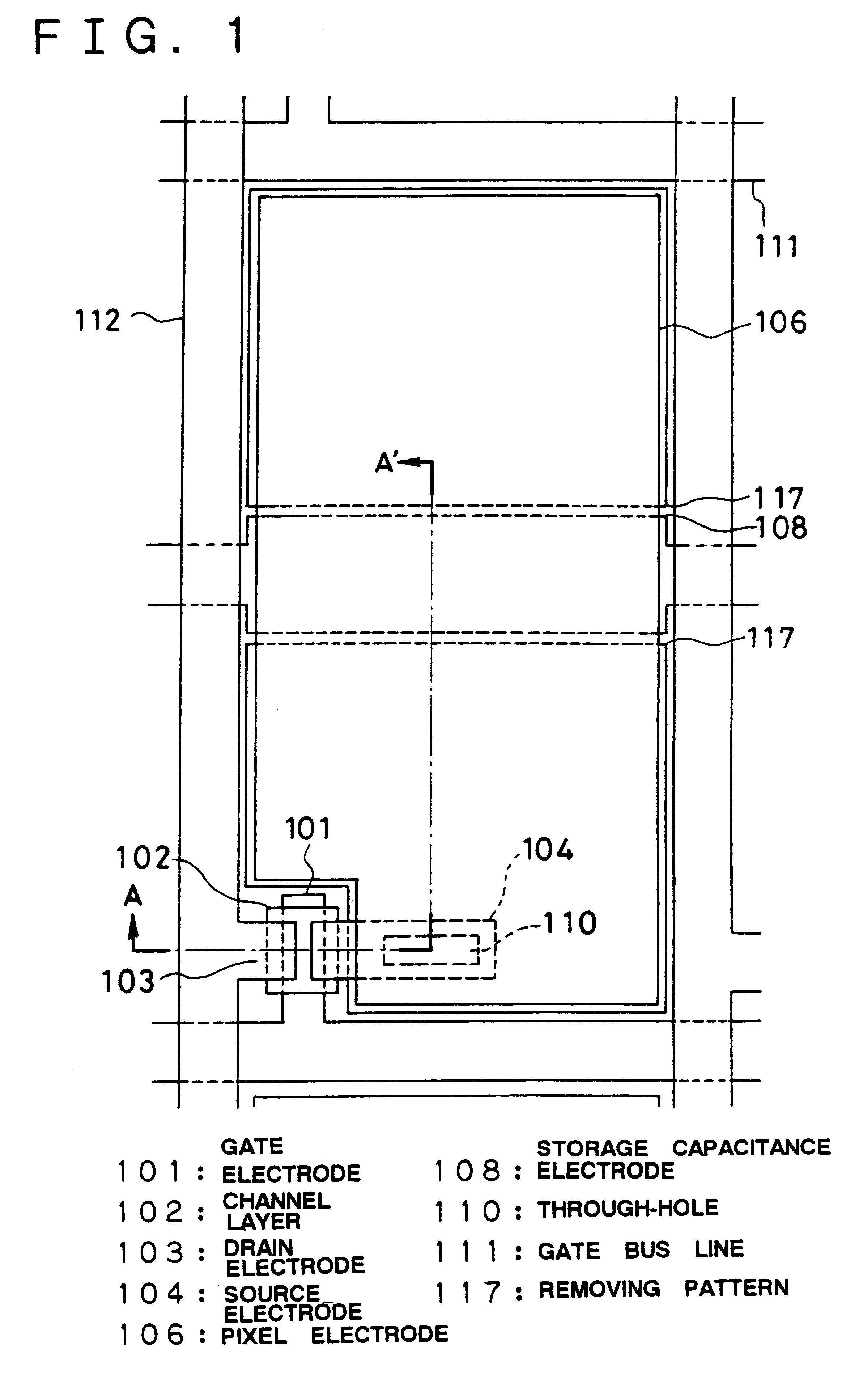
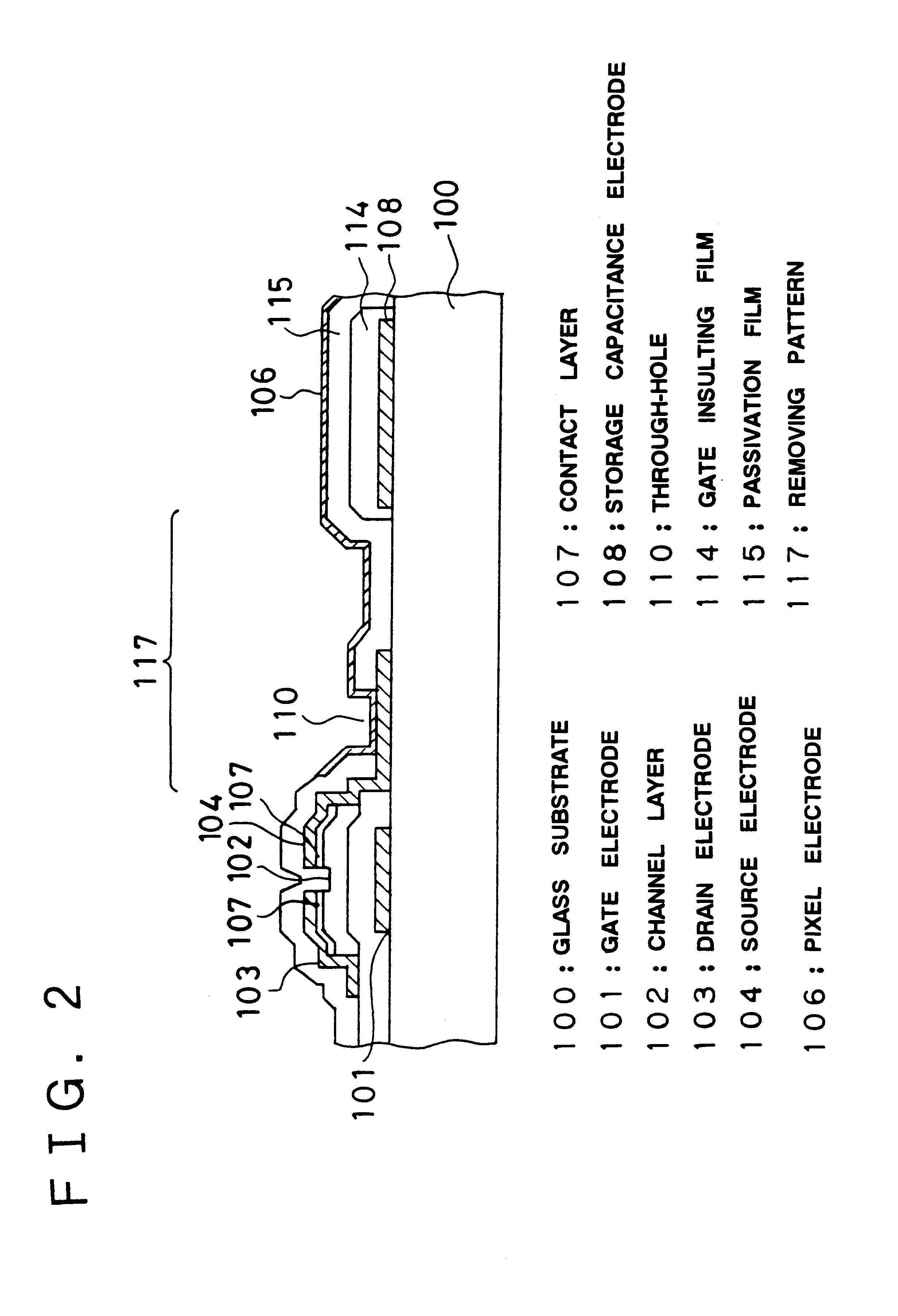
FIGS. 1 and 2 show a plan view illustrating a first embodiment of a thin-film transistor array of the present invention and a cross-sectional view taken along line A-A' of FIG. 1, respectively.

Referring to FIGS. 1 and 2, the structure of the first embodiment of the present invention is explained.

In the first embodiment of the present invention, there exist two layers, namely a gate insulating film 114 and a passivation film 115 as upper layers of the gate electrode 101 and the gate bus line 111. However, the insulating film for the pixel electrode disposed below the pixel electrode 106 is made up only of the passivation film 115. Namely 117 termed as "removing pattern" designates an area where the gate insulating film 114 has been removed.

The passivation film 115, as an insulating film, is interposed between a drain bus line 112 and the pixel electrode 106. Namely, the drain bus line 112 is disposed below the passivation film 115, whereas the pixel electrode 106 is above the passiva...

second embodiment

the present invention is characterized in that the storage capacitance electrode 108 is used simultaneously as the gate bus line 101 and is otherwise the same as the above-described first embodiment.

In the second embodiment of the present invention, the insulating film for the pixel electrode, extending over a partial area 117 lying below the pixel electrode 106, is constituted solely by the passivation film 115, as in the first embodiment, so that residual a-Si produced due to patterning defects during the island forming step can be removed simultaneously. This reduces occurrences of defects of semi-bright spots, otherwise caused by increased parasitic capacitance between the drain bus line 112 and the pixel electrode 106 on interconnection to the drain bus line 112 to suppress the reject ratio to improve the production yield.

Moreover, since there is the insulating passivation film 115 as a boundary separating film between the drain bus line 112 and the end of the pixel electrode 1...

third embodiment

the present invention is characterized in that, in removing the gate insulating film 114 lying below the pixel electrode of each unit pixel, there is formed a removing pattern 117 in the form of a slot a few micrometers in width along the drain bus line 112 and is otherwise the same as the above-described first embodiment.

For illustrating the operation and result of the third embodiment of the present invention, FIG. 10 shows a plan view illustrating the state of residual a-Si produced on a pixel. FIG. 11 shows a cross-sectional view taken along line E-E' of FIG. 10.

With the third embodiment of the present invention, the gate insulating film 114 of a partial area 117 lying below the pixel electrode is removed in the contact step in the form of slits several micrometers in width along the drain bus line 112 for simultaneously removing residual a-Si 116 produced due to patterning defects during the island step. This reduces occurrences of point defects of semi-bright spots otherwise p...


PUM

PropertyMeasurementUnit
transparentaaaaaaaaaa
n-type semiconductoraaaaaaaaaa
shapeaaaaaaaaaa

Abstract

A high-quality thin-film transistor array. The gate insulating film below the pixel electrode is etched off in its entirely or along a slit extending along a drain bus line in order to simultaneously remove the residual a-Si produced due to defective patterning. The insulating film is interposed between a drain bus line and a pixel electrode to form a boundary separating layer therebetween. The reject ratio is suppressed by reducing the occurrence of point defects of semi-bright spots, ascribable to capacitative coupling to the pixel electrodes as a result of interconnection of the residual a-Si produced by defective patterning to the drain bus line.

Description

This invention relates to a thin-film transistor array and, more particularly, to a thin-film transistor array that can be used with advantage for an active matrix liquid crystal display panel.DISCUSSION ON THE RELATED ARTThe following specific analyses have been given on the related art by the inventors in the course of the investigation toward the present invention.An active matrix type liquid crystal display device, employing a thin-film transistor (`TFT`) as a switching device, is made up of a TFT substrate comprised of a matrix array of TFTs and pixel electrodes and an opposing substrate electrode, arranged opposing the TFT substrate with a liquid crystal material interposed in-between. The opposing substrate electrode includes a light-shielding film (so-called black matrix), a color filter and a common electrode.FIG. 15 shows a plan view illustrating the structure for one pixel of a typical thin-film transistor array, and FIG. 16 shows a cross-sectional view taken along line G...

Claims


Application Information

Patent Timeline
Patent Type & Authority Patents(United States)
IPC IPC(8): H01L21/70H01L27/12H01L21/84G02F1/136G02F1/1343G02F1/1368H01L21/336H01L21/77H01L29/786
CPCH01L27/1214H01L27/1244
Inventor TAGUCHI, NAOYUKIOHI, SUSUMU
Owner NEC LCD TECH CORP
Why Eureka
Try Eureka