Latching apparatus and also medical imaging apparatus with the latching apparatus

a technology of latching apparatus and latching device, which is applied in the field of latching apparatus, can solve the problems that the requirements have so far only been met in an unsatisfactory manner, and achieve the effect of preventing undesired distortion of individual cladding components and requiring a small amount of effor

Inactive Publication Date: 2013-09-12
SIEMENS HEALTHCARE GMBH
View PDF17 Cites 0 Cited by
  • Summary
  • Abstract
  • Description
  • Claims
  • Application Information

AI Technical Summary

Benefits of technology

[0007]It is proposed that the at least one latching unit is disposed entirely on the first cladding component for a latching connection with the at least one second cladding component. This enables housing cladding to be disposed in a constructionally simple manner around a detector unit of a medical imaging apparatus. In addition, as a result of the latching unit, it is simple to dismantle the cladding components for service work for example. Furthermore the latching unit can be disposed in this way in a compact manner within the latching apparatus, in which case additional installation steps and costs can be saved here because of the simple arrangement on only one cladding component. Operation of the latching apparatus without tools can be achieved which, because of the latching connection, makes it possible to easily install or dismantle cladding components at any time.
[0021]The disclosed latching apparatus is suitable for attachment of large-surface cladding components, as can be used in the housing cladding of medical imaging devices, such as magnetic resonance devices. In this way a housing cladding and / or a medical imaging apparatus, especially a magnetic resonance apparatus, can be obtained in which the individual cladding components can be disposed simply and with little effort within the housing cladding. In this case thin-wall cladding components can also be disposed within the housing cladding and in such cases undesired distortion of the individual cladding components can be prevented.

Problems solved by technology

With cladding components having a large surface area, these requirements can lead to a conflict, since these large-surface cladding components, because of their weight, are to be securely disposed, such as on the one hand being securely screwed on for example.
These requirements have thus far only been met in an unsatisfactory manner by using commercially-available screw connections to attach the cladding components and screwing the cladding components to the medical imaging apparatus.

Method used


Image

  • Latching apparatus and also medical imaging apparatus with the latching apparatus
  • Latching apparatus and also medical imaging apparatus with the latching apparatus
  • Latching apparatus and also medical imaging apparatus with the latching apparatus

Examples


Embodiment Construction

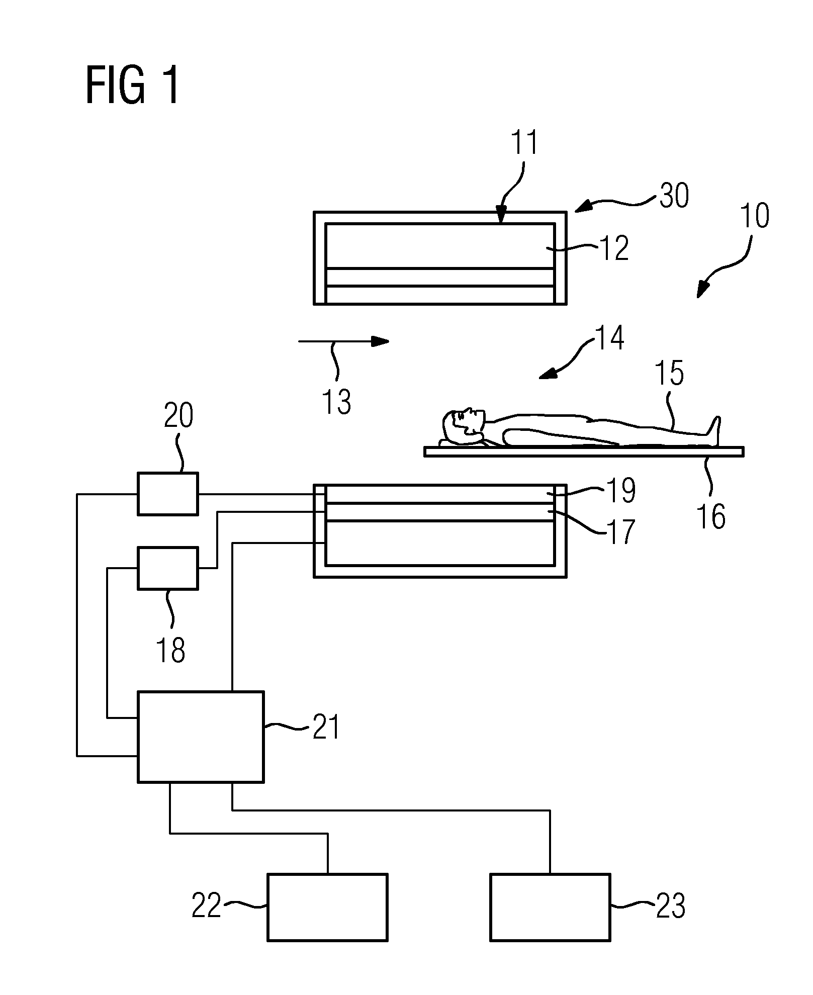
[0030]FIG. 1 shows a schematic of a disclosed medical imaging apparatus which is formed by a magnetic resonance apparatus 10. As an alternative to this the medical imaging apparatus can also be formed by a CT apparatus or a PET apparatus and / or by further medical apparatuses appearing sensible to the person skilled in the art.

[0031]The magnetic resonance apparatus 10 comprises a magnet unit 11 with a main magnet 12 for generating a strong and constant main magnetic field 13. In addition the magnetic resonance apparatus 10 has a cylindrical receiving area 14 for receiving a patient 15, wherein the receiving area 14 is enclosed in a circumferential direction by the magnet unit 11. The patient 15 can be introduced by a patient couch 16 of the magnetic resonance apparatus 10 into the receiving area 14. The patient couch 16 is disposed for this purpose movably within the magnetic resonance apparatus 10. Furthermore the magnetic resonance apparatus 10 has housing cladding 30 surrounding t...


PUM


Abstract

A latching apparatus for housing cladding of a medical imaging device is provided. The latching apparatus has at least one first cladding component, a second cladding component and at least one latching unit. The at least one latching unit is disposed entirely on the first cladding component for a latching connection with the at least one second cladding component.

Description

CROSS REFERENCE TO RELATED APPLICATIONS[0001]This application claims priority of German application No. 10 2011 082 369.7 filed Sep. 8, 2011, which is incorporated by reference herein in its entirety.FIELD OF INVENTION[0002]The present application relates to a latching apparatus, such as for housing cladding of a medical imaging apparatus, with at least one first cladding component and at least one second cladding component and at least one latching unit.BACKGROUND OF INVENTION[0003]Various demands in respect of design, service and safety are imposed on the housing cladding for the layout of housing cladding, such as for medical imaging devices such as magnetic resonance apparatuses or computed tomography apparatuses etc. Thus for example, because of design aspects, no screw connections of the housing cladding should be visible from the outside. However, because of service aspects, all cladding components of the housing cladding should still be disposed to allow easy installation an...

Claims


Application Information

Patent Timeline
Patent Type & Authority Applications(United States)
IPC IPC(8): F16B2/22
CPCG01R33/28Y10T403/602F16B2/22A61B5/055Y10T292/0824G01R33/3802A61B5/704
Inventor KASPER, PETERMACIEJEWSKI, BERND
Owner SIEMENS HEALTHCARE GMBH
Why Eureka
Try Eureka