Wind turbine blade structures, lifting assemblies and methods of blade handling

a technology of wind turbine blades and components, applied in the direction of propellers, propulsive elements, water-acting propulsive elements, etc., can solve the problems of slings exerting potentially damaging forces on blade parts, relative sliding, and increasing repair or replacement problems, so as to limit the stress at the connection point

Active Publication Date: 2013-09-12
VESTAS WIND SYST AS
View PDF5 Cites 32 Cited by
  • Summary
  • Abstract
  • Description
  • Claims
  • Application Information

AI Technical Summary

Benefits of technology

[0015]In a still further form the internal load-bearing structure includes a pair of spaced beams or webs, which webs may be a part of a spar structure, each provided with a lateral opening to receive therebetween a lifting bar of a lifting assembly. The lateral openings are again preferably provided at or near the neutral axis of the blade in order to limit the stresses at the connection points.

Problems solved by technology

The handling of these large blades during manufacture, transport to the turbine site, during installation, repair or replacement becomes increasingly problematic.
The use of such slings is potentially problematic in that these slings do not make a direct fixed connection to the blade, and are thereby susceptible to relative sliding of the blade within the sling.
Moreover, if not carefully arranged, the slings can exert potentially damaging forces on parts of the blades, particularly the relatively delicate trailing edge.
If the blade is provided with dynamically operative structures such as trailing edge flaps, these are particularly susceptible to damage.
In addition, there is the potential for damage to the blade's structural integrity, in that the blade structure is designed in order to accommodate loading during normal use when in its operating position mounted at its root end on the rotor hub, and is not designed having particular regard to loads during lifting when constrained at or near the central region of the blade.

Method used


Image

  • Wind turbine blade structures, lifting assemblies and methods of blade handling
  • Wind turbine blade structures, lifting assemblies and methods of blade handling
  • Wind turbine blade structures, lifting assemblies and methods of blade handling

Examples


Embodiment Construction

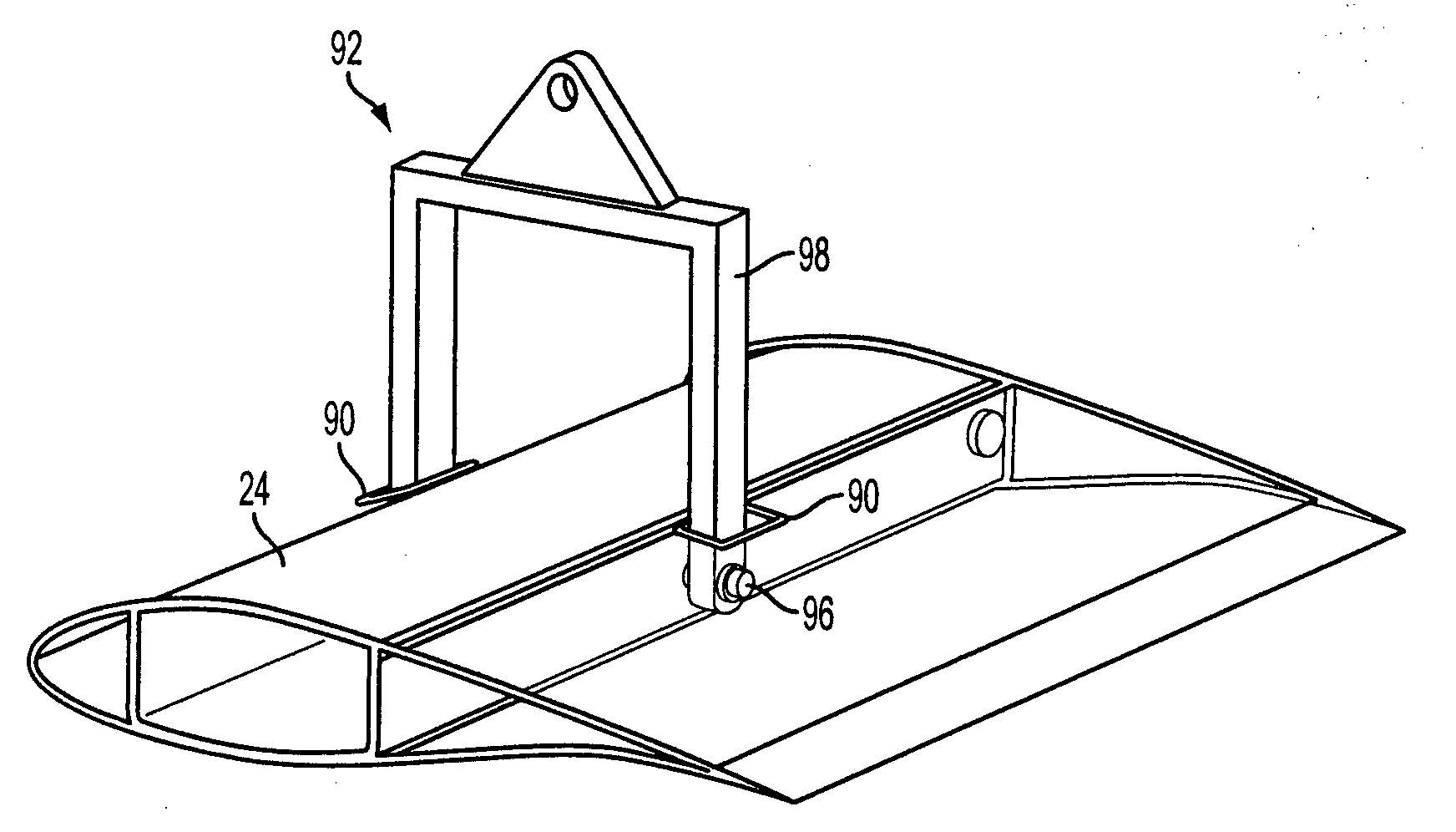
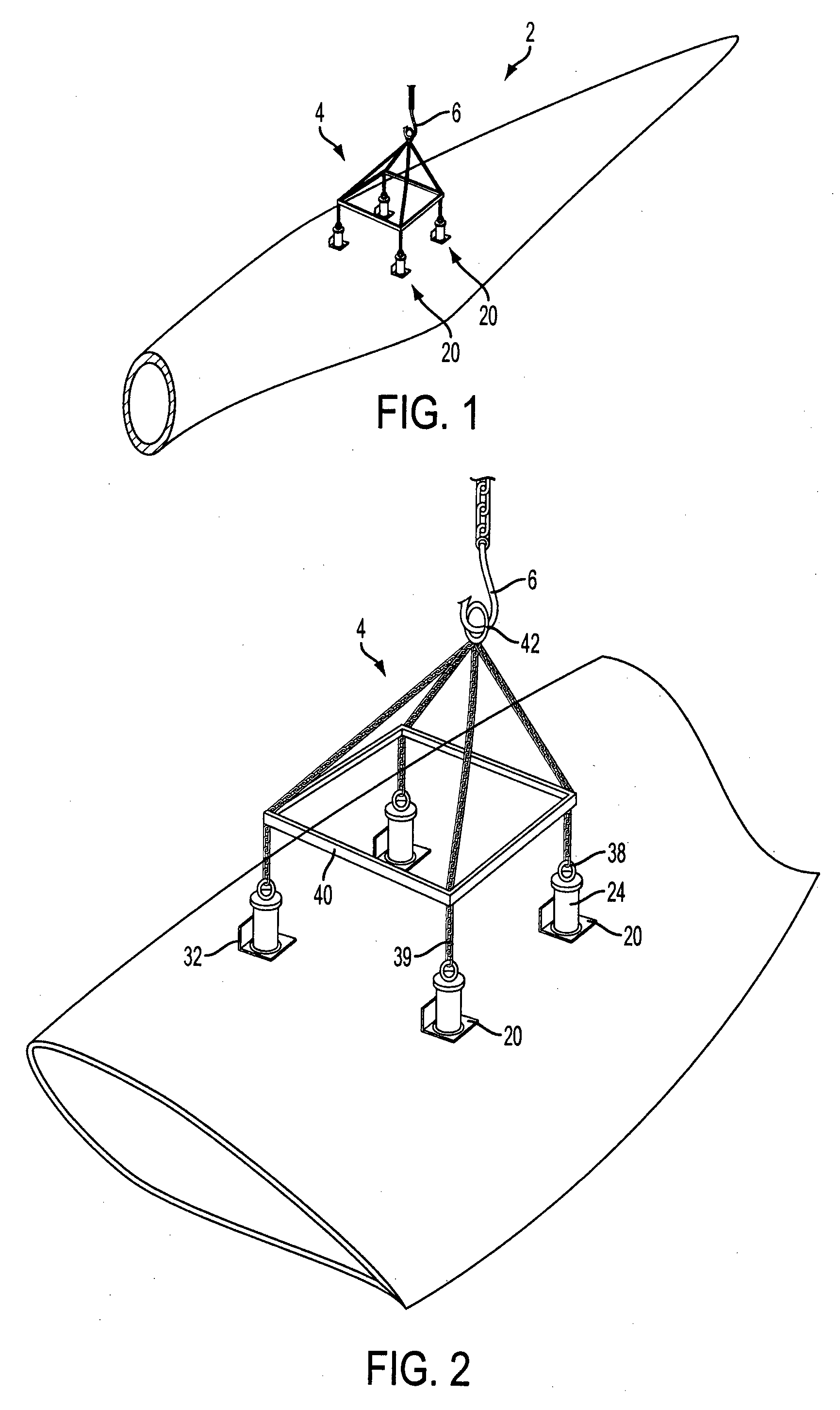
[0043]Turning to the drawings, FIG. 1 shows a wind turbine blade, generally indicated 2, being lifted by a lifting assembly 4 which is connected to a lifting hook 6 suspended from a crane (not shown). As indicated in FIGS. 1 and 2, the blade is provided with lifting points 20, most preferably four such lifting points, provided spaced equidistantly about the blade's centre of gravity and to which the lifting assembly is attached, whereby when lifted the blade adopts a balanced orientation.

[0044]As an alternative to four such lifting points, a pair of lifting points could be utilised, arranged equidistantly about the centre of gravity. As a further alternative, the lifting points could be spaced in pairs arranged along the blade, for example one pair could be located at a position between the centre of gravity and the root end, and a second pair between the centre of gravity and the tip end. As a still further alternative, further additional lifting points could be provided so that 6 ...


PUM


Abstract

A wind turbine blade 2 is formed with structures allowing its lifting by a lifting apparatus 4, the blade comprising upper and lower blade shells and an internal load-bearing structure comprising an internal spar 16 or internal webs, a plurality of lifting points 20 arranged about the blade centre of gravity, comprising openings for receiving lifting members 24 of a lifting apparatus insertable therein into structures 22 secured to the load-bearing structure, and with a locking connection being established between the lifting members 24 and the load-bearing structure 16.

Description

FIELD OF THE INVENTION[0001]The present invention relates to lifting assemblies for handling wind turbine blades, to blades adapted to be lifted with such an assemblies, and to methods of blade handling.BACKGROUND OF THE INVENTION[0002]With the growing acceptance of wind turbines as a commercially viable source of energy, and the continuous drive for reducing the cost of the produced energy, the size of turbines continues to increase. At the time of writing, all major turbine manufacturers have turbines in the 2-3MW range, and most are developing larger models in the 3-7MW range. Such models will typically have rotor blades which are in the region of 50 to 70 m or even larger, and weighing in the region of 5-7 tonnes or more.[0003]The handling of these large blades during manufacture, transport to the turbine site, during installation, repair or replacement becomes increasingly problematic. Conventional handling techniques involve the use of slings which encircle the blades in the c...

Claims


Application Information

Patent Timeline
Patent Type & Authority Applications(United States)
IPC IPC(8): F03D1/06F03D1/00B66C1/10F03D11/00
CPCF03D1/003F03D1/005F03D11/00F05B2230/61Y02E10/721B66C1/108F03D1/001F03D1/0633Y02E10/722F03D1/0675F03D13/40F03D80/00F03D80/50Y02E10/72Y02P70/50F03D80/70
Inventor BECH, ANTONHANCOCK, MARKTHOMSEN, PETER FRANS
Owner VESTAS WIND SYST AS
Why Eureka
Try Eureka