
Vessel propulsion apparatus

Active Publication Date: 2013-09-12
YAMAHA MOTOR CO LTD
View PDF1 Cites 2 Cited by
  • Summary
  • Abstract
  • Description
  • Claims
  • Application Information

AI Technical Summary

Benefits of technology

The patent describes a new design for a vessel propulsion system that allows for smooth and efficient operation in both forward and reverse drives. The system uses a deflector to guide the water stream in opposite directions, allowing the vessel to turn smoothly without experiencing any differences in steering or turning during forward or reverse drives. The design also allows for the water stream to be tilted further out than the maximum rotation angle of the deflector, which results in a larger force for propelling the vessel in reverse. Overall, the system provides better performance and control for the vessel's propulsion.

Problems solved by technology

However, the jet propulsion apparatus according to U.S. Pat. No. 5,304,078 cannot generate a water stream that is tilted further outward than a maximum rotation angle of the deflector with respect to the nozzle, and thus, to further increase a right / left direction component of thrust, an output of an engine or other power source must be increased.

Method used


Image

  • Vessel propulsion apparatus
  • Vessel propulsion apparatus
  • Vessel propulsion apparatus

Examples


first preferred embodiment

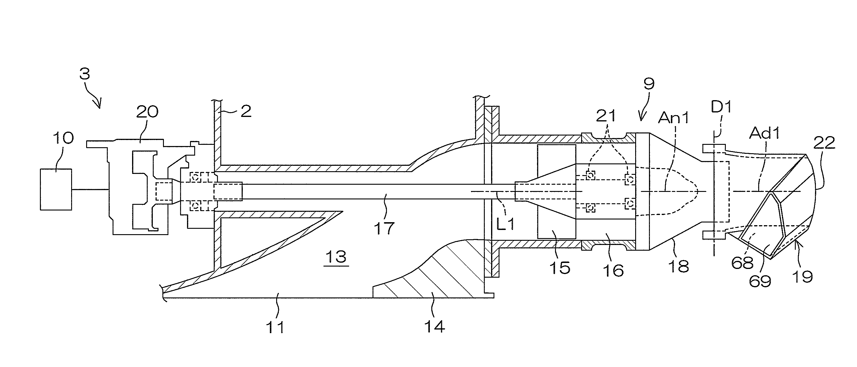
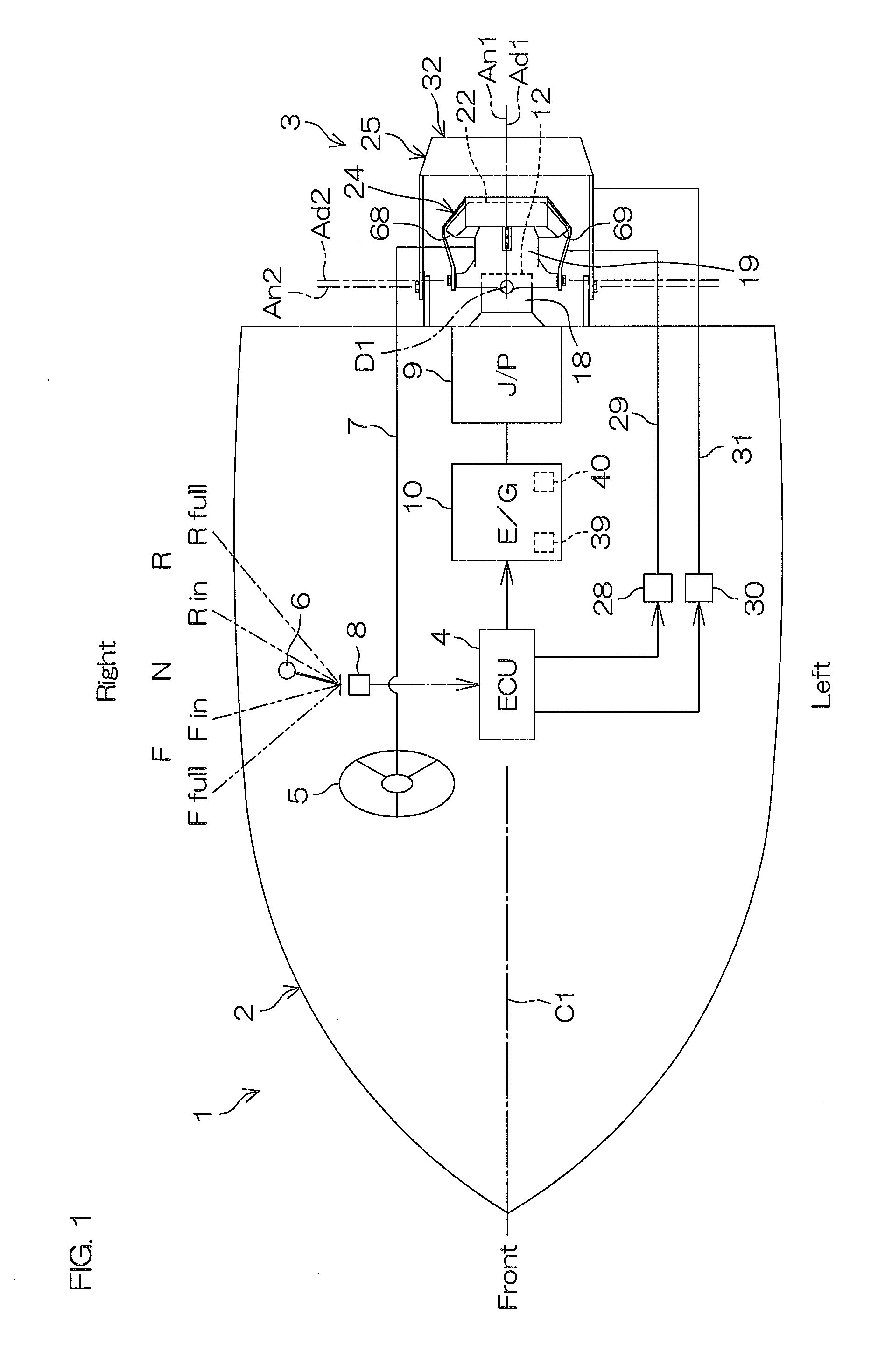
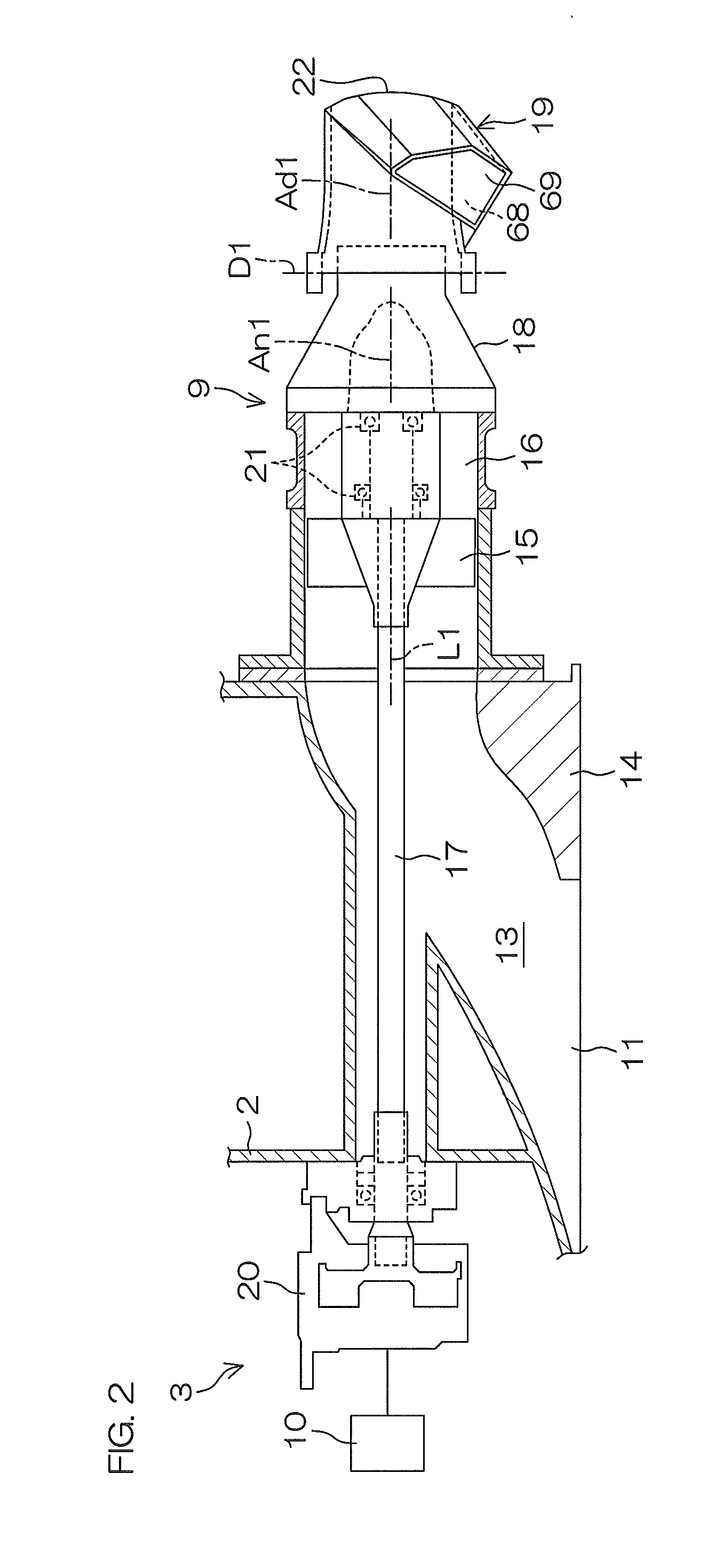
[0068]FIG. 1 is a schematic plan view of a vessel 1 according to a first preferred embodiment of the present invention. FIG. 2 is a partial sectional view of a vessel propulsion apparatus 3 according to the first preferred embodiment of the present invention. FIG. 3 is a schematic side view of an R bucket 24 and an F bucket 25. FIG. 4 is a schematic rear view of the R bucket 24 and the F bucket 25. Illustrations of the R bucket 24 and the F bucket 25 are omitted in FIG. 2.

[0069]As shown in FIG. 1, the vessel 1 includes a hull 2, the vessel propulsion apparatus 3 that drives the hull 2 forward and in reverse, and an ECU 4 (electronic control unit) that controls the vessel propulsion apparatus 3. Further, the vessel 1 includes a handle 5 operated by a vessel operator to change a turning angle of the vessel 1 and a lever 6 operated by the vessel operator to change an output of the vessel propulsion apparatus 3.

[0070]As shown in FIG. 1, the vessel propulsion apparatus 3 is disposed at a...

second preferred embodiment

[0136]A second preferred embodiment of the present invention shall now be described. In FIG. 12A to FIG. 14D described below, component portions equivalent to respective portions shown in FIG. 1 to FIG. 11E are provided with the same reference symbols as in FIG. 1 to FIG. 11E, and description thereof shall be omitted.

[0137]FIG. 12A is a schematic plan view describing water flow in a state in which an R bucket 224 is positioned at a closed position and a deflector 219 is positioned at a straight drive position. FIG. 12B is a schematic plan view describing water flow in a state in which the R bucket 224 is positioned at the closed position and the deflector 219 is positioned at a left side. In FIG. 12A and FIG. 12B, a vessel propulsion apparatus 203 is shown in a transparent state. Thick line arrows shown in FIG. 12A and FIG. 12B indicate directions of water streams.

[0138]With the exception of the deflector, the R bucket, and the F bucket, the vessel propulsion apparatus 203 according...

third preferred embodiment

[0158]A third preferred embodiment of the present invention shall now be described. In FIG. 15 to FIG. 19D below, component portions equivalent to respective portions shown in FIG. 1 to FIG. 14E are provided with the same reference symbols as in FIG. 1 to FIG. 14E, and description thereof shall be omitted.

[0159]FIG. 15 is a schematic plan view of a vessel propulsion apparatus 303 according to the third preferred embodiment of the present invention. FIG. 16A is a schematic front view of a bucket 363. FIG. 16B is a schematic perspective view of a central portion of an R bucket 324.

[0160]With the exception of the deflector, the R bucket, and the F bucket, the vessel propulsion apparatus 303 according to the third preferred embodiment preferably has the same or substantially the same arrangement as the vessel propulsion apparatus 3 according to the first preferred embodiment. That is, as shown in FIG. 16A, the vessel propulsion apparatus 303 includes a bucket 363 in place of the R bucke...


PUM


Abstract

A vessel propulsion apparatus includes a nozzle, a deflector, a reverse bucket, and a guide. In a state in which the reverse bucket is positioned at a closed position and the deflector is positioned at a straight drive position, the guide generates a right branch stream flowing in an obliquely forward right direction and a left branch stream flowing in an obliquely forward left direction. In a state in which the reverse bucket is positioned at the closed position and the deflector is positioned at a right side, the guide generates the left branch stream. In a state in which the reverse bucket is positioned at the closed position and the deflector is positioned at a left side, the guide generates the right branch stream.

Description

SUMMARY OF THE INVENTION[0001]The inventors of preferred embodiments of the present invention described and claimed in the present application conducted an extensive study and research regarding a vessel propulsion apparatus, such as the ones described above, and in doing so, discovered and first recognized new unique challenges and previously unrecognized possibilities for improvements as described in greater detail below.[0002]Specifically, with U.S. Pat. No. 5,304,078, water is jetted rearward from the nozzle in a state in which the reverse bucket is lowered and the deflector is tilted to the right or left. Water that flows into the deflector in this state is jetted obliquely forward to the right or obliquely forward to the left from the deflector. A vessel is thereby propelled obliquely rearward to the right or obliquely rearward to the left. However, the jet propulsion apparatus according to U.S. Pat. No. 5,304,078 cannot generate a water stream that is tilted further outward t...

Claims


Application Information

Patent Timeline
IPC IPC(8): B63H11/11
CPCB63H11/11
Inventor MINOURA, MINORUOOTA, NOBUHARU
Owner YAMAHA MOTOR CO LTD
Features
  • Generate Ideas
  • Intellectual Property
  • Life Sciences
  • Materials
  • Tech Scout
  • Unparalleled Data Quality
  • Higher Quality Content
  • 60% Fewer Hallucinations
Learn More