Device for Supplying Fuel to Engine

Inactive Publication Date: 2013-09-19
KUBOTA LTD
View PDF11 Cites 4 Cited by
  • Summary
  • Abstract
  • Description
  • Claims
  • Application Information

AI Technical Summary

Benefits of technology

[0049]According to this configuration, even when air is included in the fuel that is collected in the recessed reservoir unit, it is possible for the air to rise through the hollow space of the cylindrical body and be discharged

Problems solved by technology

In the apparatus described in Japanese Laid-open patent Application 2007-16658, because preventing the clogging of the filter necessitates the furnishing of the circulation va

Method used


Image

  • Device for Supplying Fuel to Engine
  • Device for Supplying Fuel to Engine
  • Device for Supplying Fuel to Engine

Examples


first embodiment

[0064]Embodiments of a fuel supply device for an engine as in the present invention shall be described on the basis of the accompanying drawings.

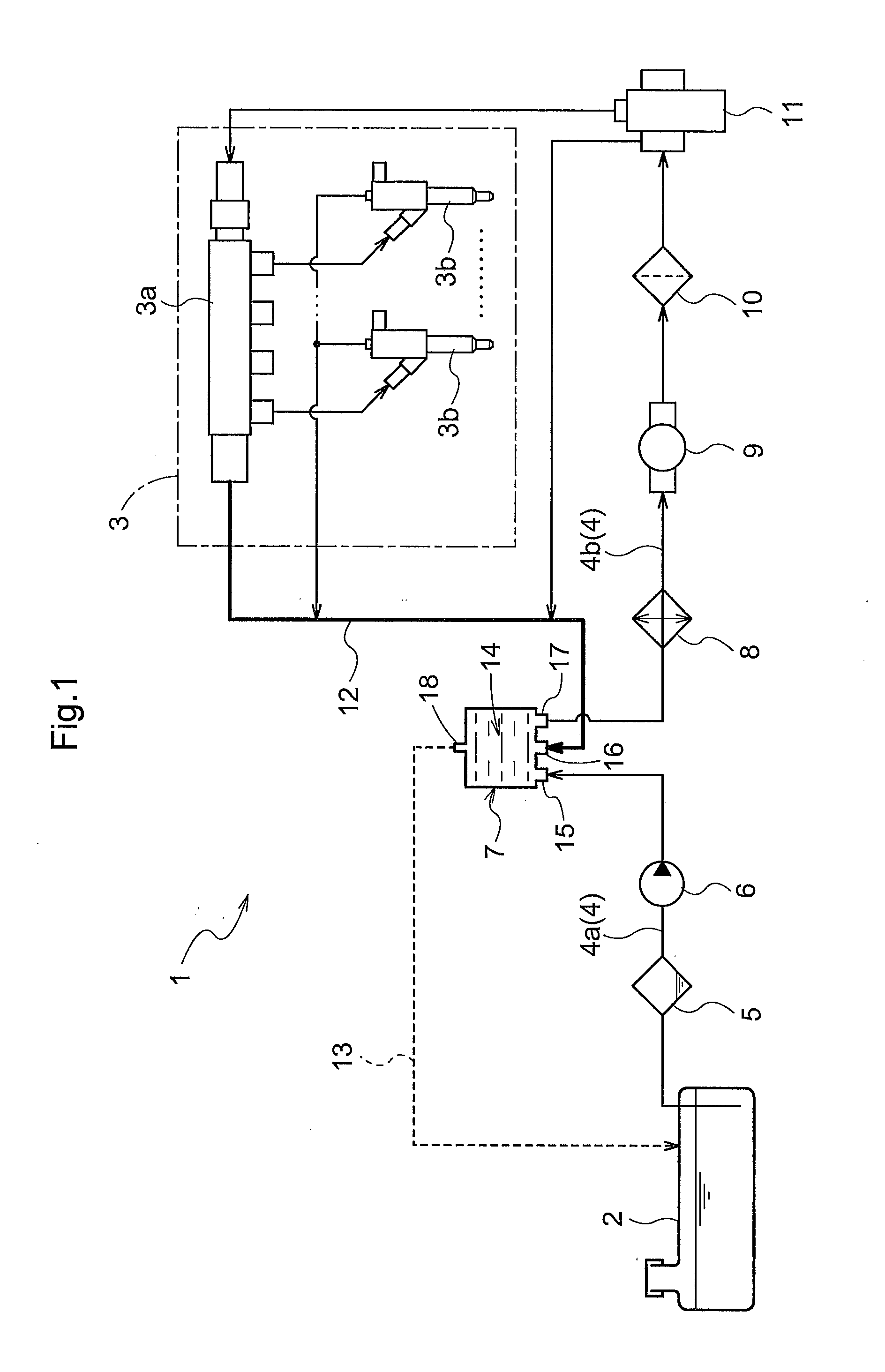
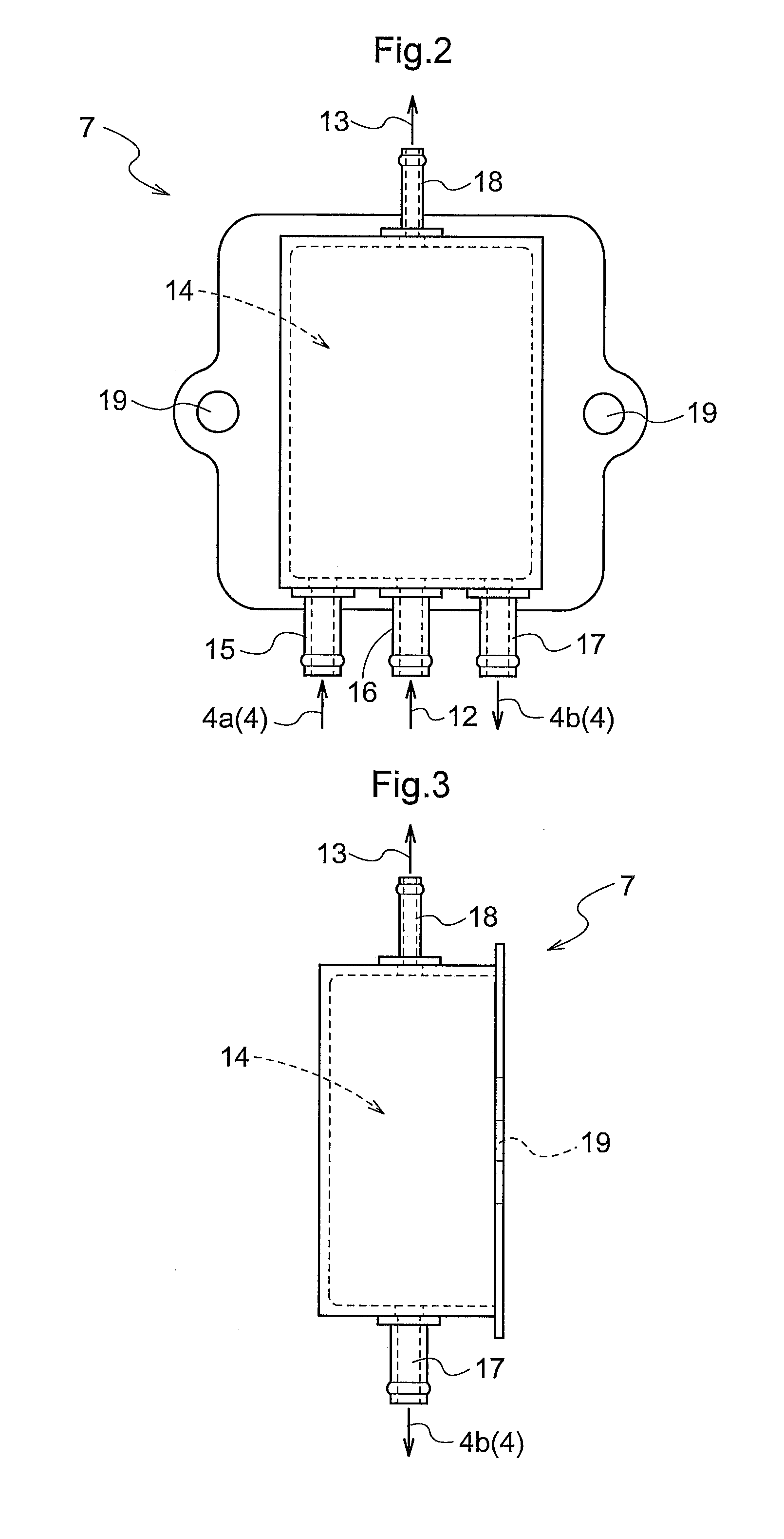
[0065]A fuel supply device 1 for an engine, as illustrated in FIG. 1, is provided with a fuel supply route 4 for supplying to an engine 3 fuel that is collected in a fuel tank 2. Provided to the fuel supply route 4 are a moisture removal unit 5, an electromagnetic pump 6 (equivalent to a second fuel pump), a merge and discharge unit 7, a cooling unit 8, a feed pump 9 (equivalent to a third fuel pump), a filter 10, and a supply pump 11 (equivalent to a first fuel pump), in the stated order from the upstream side in a fuel supply direction.

[0066]The engine 3 is, for example, a common-rail diesel engine provided with a rail 3a and a plurality of injectors 3b, and is adapted to be capable of electronically controlling the amount of fuel injection and the injection timing. The moisture removal unit 5 is, for example, a sedimenter, and is adapted...

second embodiment

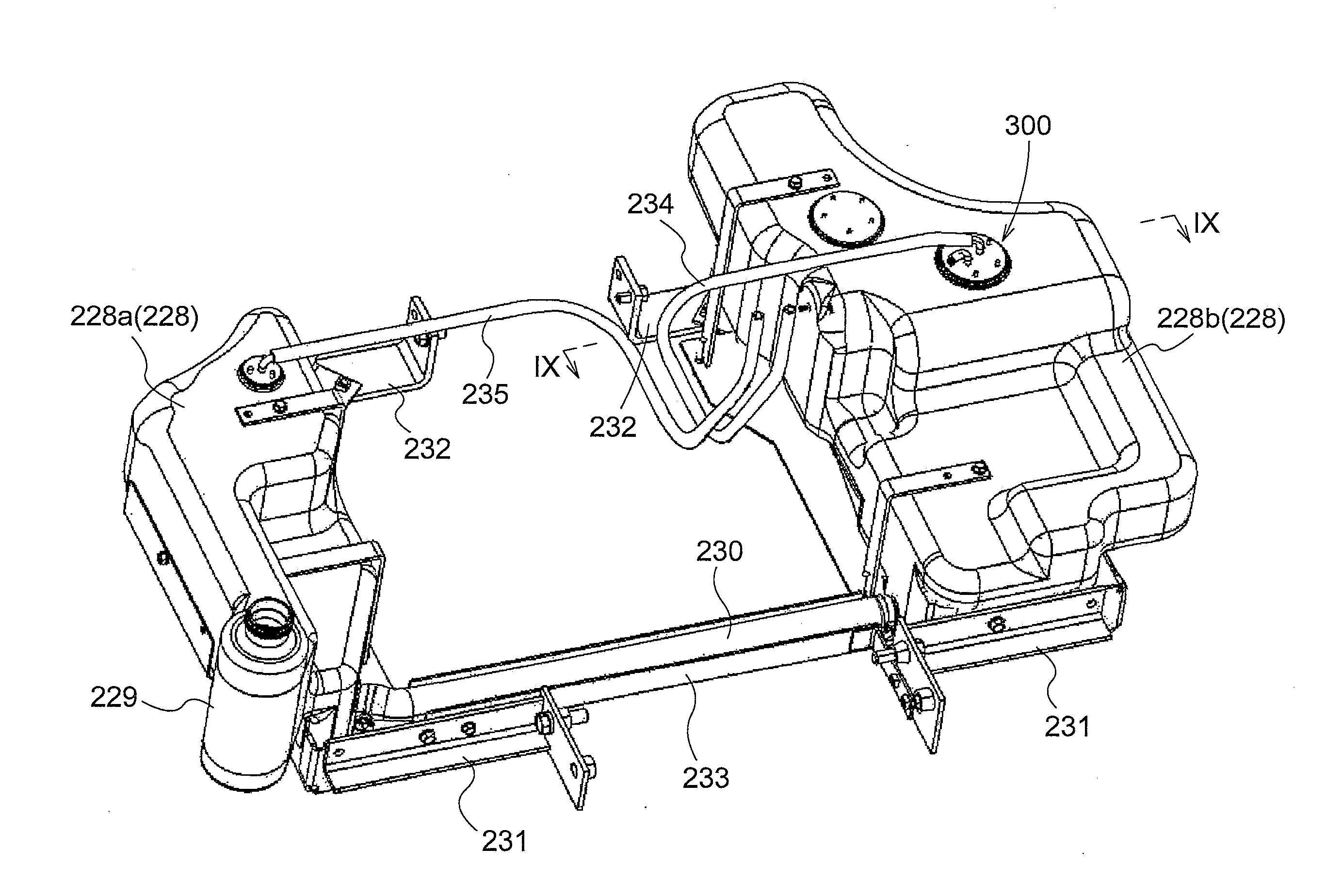
[0097]An example where an intake structure for a fuel tank as in the present invention has been adapted to a tractor shall now be described, on the basis of the accompanying drawings.

[0098]This tractor 201, as illustrated in FIG. 6, is constituted of a four-wheel drive format, provided with a traveling vehicle body 204 having a pair of left and right front wheels 202 that can be driven and operated by steering and a pair of left and right rear wheels 203 that can be driven. A hood 206 in which an engine 205 and the like are housed is provided to the front of the traveling vehicle body 204, and a cabin 209 on which a steering handle 207, a seat 208, and the like are housed is provided to the rear of the traveling vehicle body 204.

[0099]A main frame 210 extends forward from a lower part of the engine 205, and an axle case (not shown) onto which the front wheels 202 are mounted and the like are supported at the main frame 210. A clutch housing 211 extends rearward from the engine 205, ...


PUM


Abstract

A merge and discharge unit has: a reservoir unit in which fuel can be collected; a first merge unit for merging into the reservoir unit the fuel from an upstream site upstream of the merge and discharge unit on a fuel supply route; a second merge unit for merging into the reservoir unit the fuel from a first fuel return route; a first discharge unit for discharging a portion of the fuel of the reservoir unit into a downstream site downstream of the merge and discharge unit on the fuel supply route; and a second discharge unit for discharging a remaining portion of the fuel of the reservoir unit into a second fuel return route.

Description

BACKGROUND OF THE INVENTION[0001]1. Field of the Invention[0002]The present invention relates to a device for supplying fuel to an engine, the fuel supply device being provided with a fuel supply route for supplying an engine with fuel collected in a fuel tank, and a filter and a first fuel pump being provided to the fuel supply route in the stated order from the upstream side of a fuel supply direction.[0003]2. Description of the Related Art[0004]In a fuel supply device of such description, impurities included in the fuel are removed by the filter provided to the fuel supply route, and the fuel from which the impurities have been removed is supplied to the engine. Also, a fuel return route for returning fuel coming from the engine to the fuel tank is provided, so that surplus fuel in the engine is returned to the fuel tank by the fuel return route.[0005]In the fuel supply device of such description, although the impurities are removed by the filter, in a case where low-temperature ...

Claims


Application Information

Patent Timeline
IPC IPC(8): F02M37/22F02M37/24F02M37/32F02M37/54
CPCF02M37/22F02M37/0023F02M37/0058F02M31/16F02M37/0052F02M37/0082F02M37/0088Y10T137/85978F02M37/24F02M31/20F02M37/04F02M37/32F02M37/54Y02T10/12F02M37/0017F02M37/20
Inventor ONO, AKIYOSHIHISADA, TAKAHIROKAWAGUCHI, MAMORUYASUNOBE, DAISUKEADACHI, NORIFUMITSUKATANI, HISASHIKANATA, MITSUHISA
Owner KUBOTA LTD
Why Eureka
Try Eureka