Pneumatic Tire

a technology of pneumatic tires and tires, applied in the field of pneumatic tires, can solve the problems of adverse effect on steering stability on dry road surfaces, edge collapse inwards, footprint properties worsen, etc., and achieve the effects of improving steering stability, improving footprint properties, and improving footprint properties

Active Publication Date: 2013-09-19
YOKOHAMA RUBBER CO LTD
View PDF18 Cites 34 Cited by
  • Summary
  • Abstract
  • Description
  • Claims
  • Application Information

AI Technical Summary

Benefits of technology

[0018]In the center land portion sections, the footprint length in the tire circumferential direction tends to be shortest near the center in the tire width direction, and in the intermediate land portion, the footprint length in the tire circumferential direction tends to be shortest outward in the tire width direction from the center in the tire width direction. Therefore, according to the pneumatic tire of the present technology, by prescribing the above ranges for the maximum protrusion position in the land portions, the footprint properties are improved and it is possible to obtain a significant effect of improvement in the steering stability on dry road surfaces.
[0019]The pneumatic tire according to the present technology is capable of improving the footprint properties in the whole tire width direction of the tread portion, and improving the steering stability.

Problems solved by technology

However, in this case, the footprint length in a tire circumferential direction of a land portion of a ground contact region in the center in a width direction of the land portion is shortened, so the edges collapse inwards and the footprint properties worsen.
It is considered that this has an adverse effect on the steering stability on dry road surfaces.
If the maximum protruding amount of the center land portion and the intermediate land portion is less than the above range or greater than the above range, it will be difficult to improve the ground contact shape.

Method used


Image

  • Pneumatic Tire
  • Pneumatic Tire
  • Pneumatic Tire

Examples


first embodiment

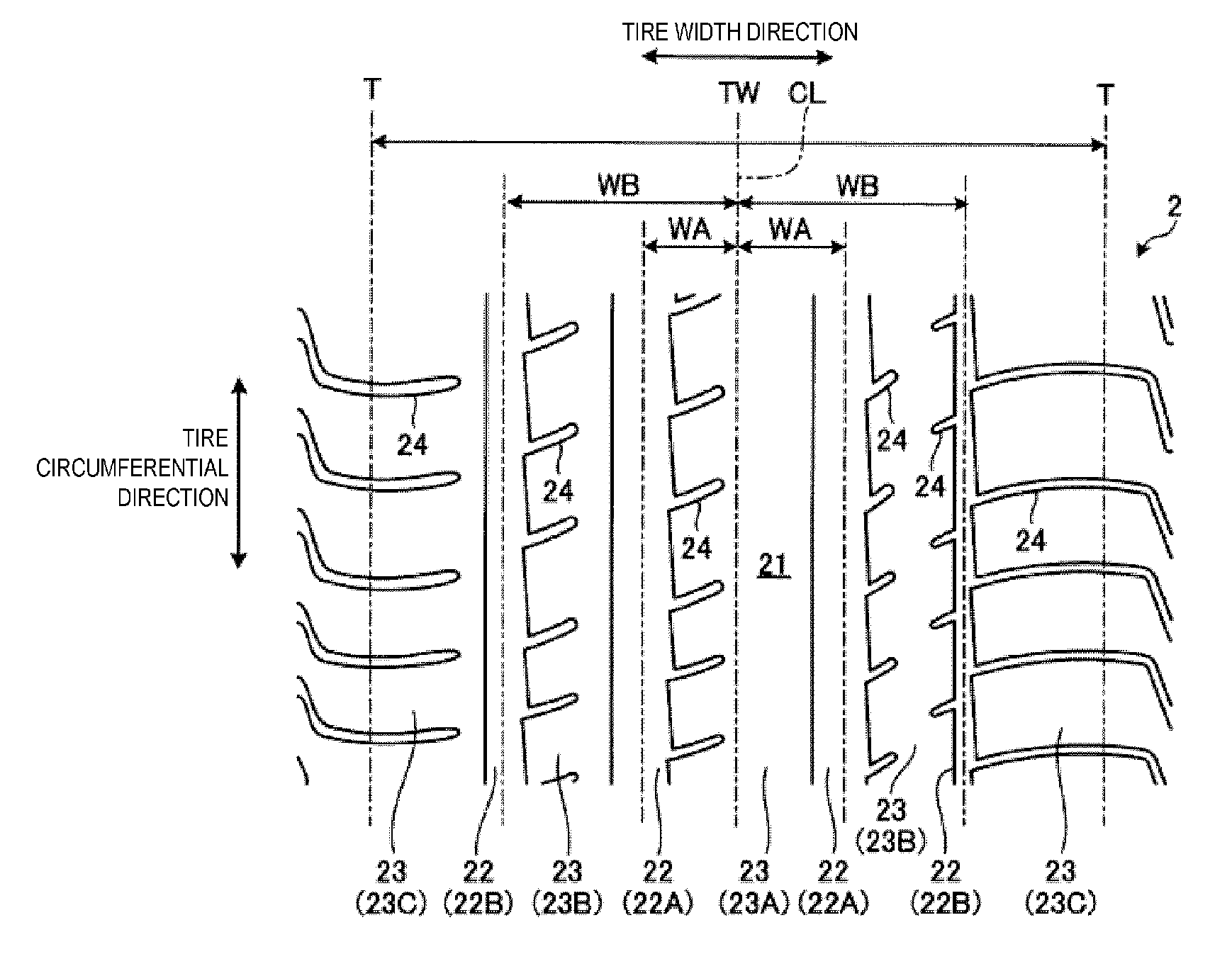
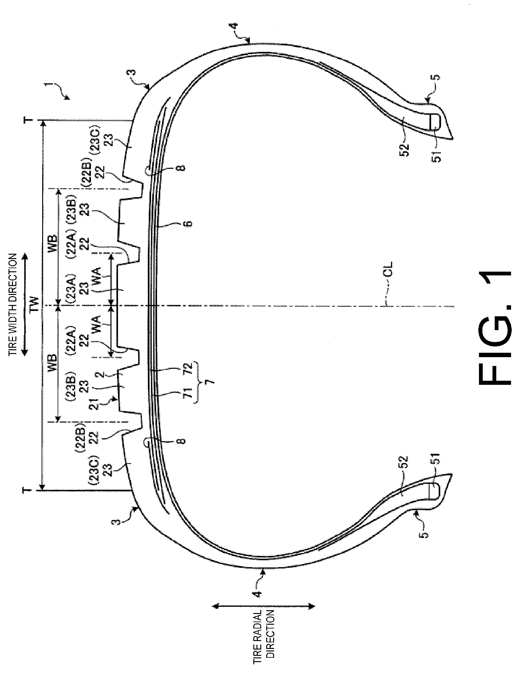
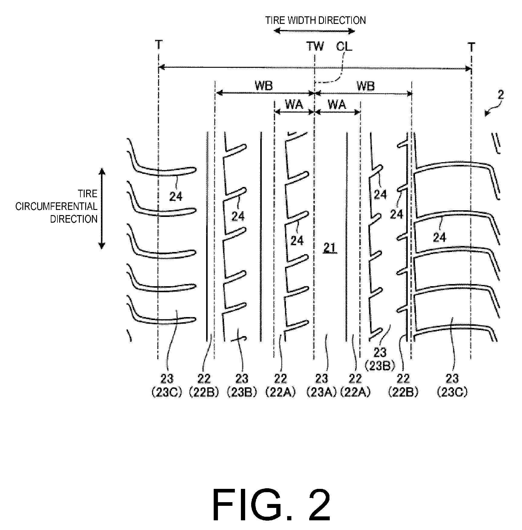
[0028]FIG. 1 is a meridian cross-sectional view of a pneumatic tire 1 according to this embodiment of the present technology. FIG. 2 is a plan view of the pneumatic tire according to this embodiment. In the following description, “tire radial direction” refers to a direction orthogonal to the rotational axis (not illustrated) of the pneumatic tire 1; “inner side in the tire radial direction” refers to the side facing the rotational axis in the tire radial direction; and “outer side in the tire radial direction” refers to the side distanced from the rotational axis in the tire radial direction. “Tire circumferential direction” refers to a circumferential direction with the rotational axis as a center axis. Additionally, “tire width direction” refers to the direction parallel to the rotational axis; “inner side in the tire width direction” refers to the side facing a tire equatorial plane CL (tire equator line) in the tire width direction; and “outer side in the tire width direction” ...

second embodiment

[0050]FIG. 4 is a plan view of the pneumatic tire according to this embodiment, and FIGS. 5 and 6 are partial enlarged meridian cross-sectional views of the tread portion of the pneumatic tire according to this embodiment. In the pneumatic tire 1 according to this embodiment, the configuration of the center land portion 23A is different from that of the pneumatic tire 1 according to the first embodiment. Therefore, constituents identical to those of the first embodiment are assigned identical reference numerals, and detailed descriptions thereof are omitted.

[0051]As illustrated in FIGS. 4 and 5, in the pneumatic tire 1 according to this embodiment, the tire width direction dimension WLA of the land portion 23A is not less than 40 mm, and a sub groove 25 extending in the tire circumferential direction is provided in the center land portion 23A. Here, sub groove 25 refers to a groove extending in the tire circumferential direction having a groove width of less than 3.0 mm, which is na...

examples

[0063]In the working examples, performance tests for steering stability on dry road surfaces were performed on a plurality of types of pneumatic tires under different conditions (see FIGS. 7 to 12).

[0064]In the performance tests, pneumatic tires having a tire size of 275 / 35R20 were assembled on a regular rim (20×9J) and inflated to the regular inner pressure (250 kPa). Then, the pneumatic tire was mounted on a test vehicle having an engine displacement of 3,500 cc.

[0065]The method of evaluating the steering stability on the dry road surfaces was to drive the test vehicle on a dry test course, and sensory evaluation was carried out by one experienced test driver for the steering properties when changing lanes and when cornering, and the stability when moving forward. This sensory evaluation was expressed as an index with a conventional example of pneumatic tire as the standard (100), so that a higher index indicated excellent steering stability.

[0066]In FIGS. 7 to 12, the pneumatic t...


PUM


Abstract

The contact patch of the center land portion partitioned by the center side main grooves protrudes outward in the tire radial direction from the overall standard profile line of the tread portion. The maximum protruding amount is not less than 1.0% and not more than 2.5% of the tire width direction dimension of the center land portion. The contact patch of the intermediate land portion partitioned by the center side main groove and the shoulder side main groove protrudes outward in the tire radial direction from the standard profile line. The maximum protruding amount is not less than 0.7% and not more than 2.0% of the tire width direction dimension of the intermediate land portion. The maximum protruding amount of the center land portion is greater than the maximum protruding amount of the intermediate land portion.

Description

PRIORITY CLAIM[0001]Priority is claimed to Japan Patent Application Serial No. 2012-057520 filed on Mar. 14, 2012.BACKGROUND[0002]1. Technical Field[0003]The present technology relates to a pneumatic tire, and more particularly relates to a pneumatic tire with improved steering stability.[0004]2. Related Art[0005]It is considered that in order to improve the steering stability on dry road surfaces, the land portion width of a tread portion should be set wide, with the aim of ensuring the tread rigidity. However, in this case, the footprint length in a tire circumferential direction of a land portion of a ground contact region in the center in a width direction of the land portion is shortened, so the edges collapse inwards and the footprint properties worsen. It is considered that this has an adverse effect on the steering stability on dry road surfaces.[0006]Conventionally, for example, in the pneumatic tire disclosed in Japanese Unexamined Patent Application Publication No. 2002-2...

Claims


Application Information

Patent Timeline
Patent Type & Authority Applications(United States)
IPC IPC(8): B60C11/11
CPCB60C11/11B60C11/1376B60C11/033B60C11/0306
Inventor KAMEDA, NORIFUMI
Owner YOKOHAMA RUBBER CO LTD
Why Eureka
Try Eureka