Photovoltaic panel racking assembly for use in connection with roof installation of panels

a photovoltaic panel and racking technology, applied in the direction of heat collector mounting/support, sustainable buildings, light and heating equipment, etc., can solve the problems of damage to the roof section, greatly hampered installation of photovoltaic panel systems, etc., to facilitate the positioning of the toggle and promote watertight sealing

Inactive Publication Date: 2013-09-19
SPONSELLER GREGORY W
View PDF0 Cites 19 Cited by
  • Summary
  • Abstract
  • Description
  • Claims
  • Application Information

AI Technical Summary

Benefits of technology

[0005]In accordance with the foregoing objects, the present invention—a photovoltaic panel racking assembly for use in connection with roof installations of photovoltaic panels—generally comprises a cylindrically shaped standoff cooperatively adjoined to a specially formed toggle through an all thread rod, or similar hardware, and having positioned at an end opposite the standoff a nut that is sized and shaped to operatively engage with the toggle to fix the relative position of one to the other. A rubber or like material gasket is also provided in order to promote watertight sealing upon installation and during use of the racking assembly. Additionally, a relief plate may be provided in order to prevent installation damage to more generally fragile roofing materials such as, for example, asphalt shingles or like composite roofing. Finally, a rubber or like material sleeve is provided in order to facilitate positioning of the toggle during installation of the racking assembly.

Problems solved by technology

After much improvement in the efficiency of photovoltaic panels and decease in cost technological cost, implementation of photovoltaic panel systems remains greatly hampered by installation costs and potential for damage to the roof section upon which a system is to be installed.

Method used


Image

  • Photovoltaic panel racking assembly for use in connection with roof installation of panels
  • Photovoltaic panel racking assembly for use in connection with roof installation of panels
  • Photovoltaic panel racking assembly for use in connection with roof installation of panels

Examples


Embodiment Construction

[0064]Although those of ordinary skill in the art will readily recognize many alternative embodiments, especially in light of the illustrations provided herein, this detailed description is exemplary of the preferred embodiment of the present invention—a photovoltaic panel racking assembly for use in connection with roof installation of photovoltaic panels, the scope of which is limited only by the claims appended hereto.

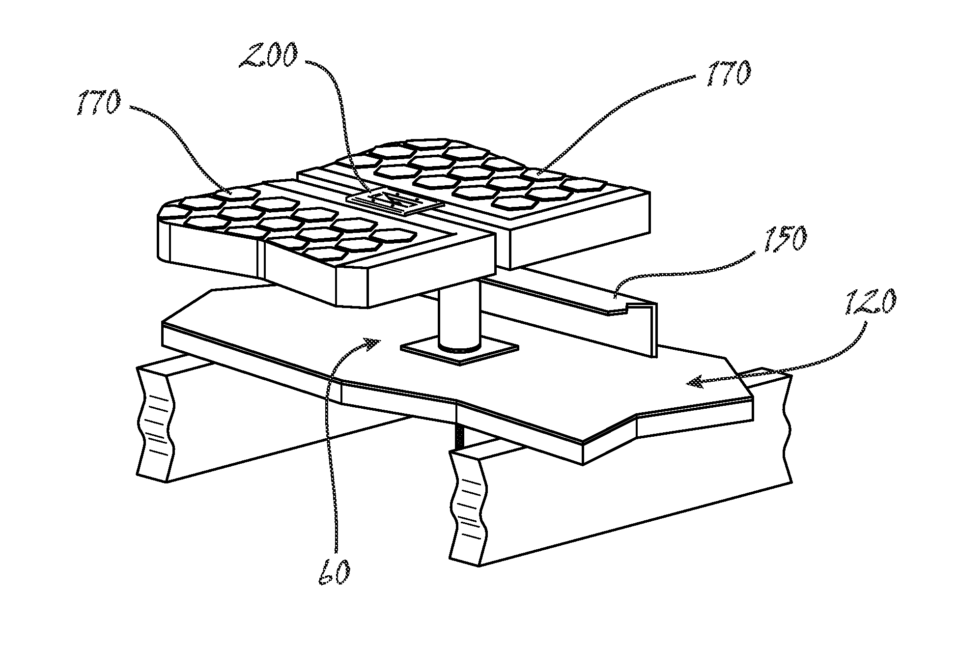
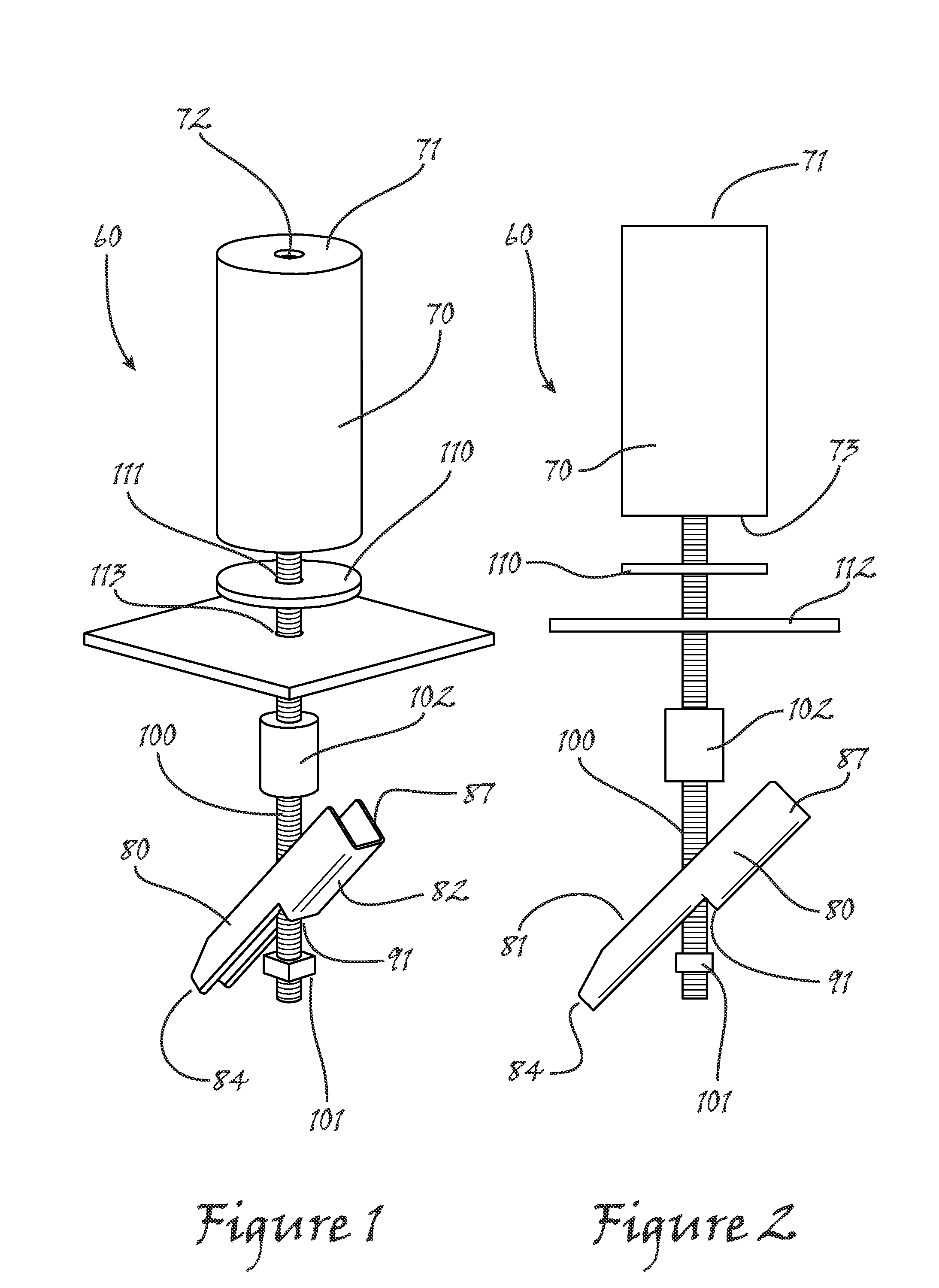
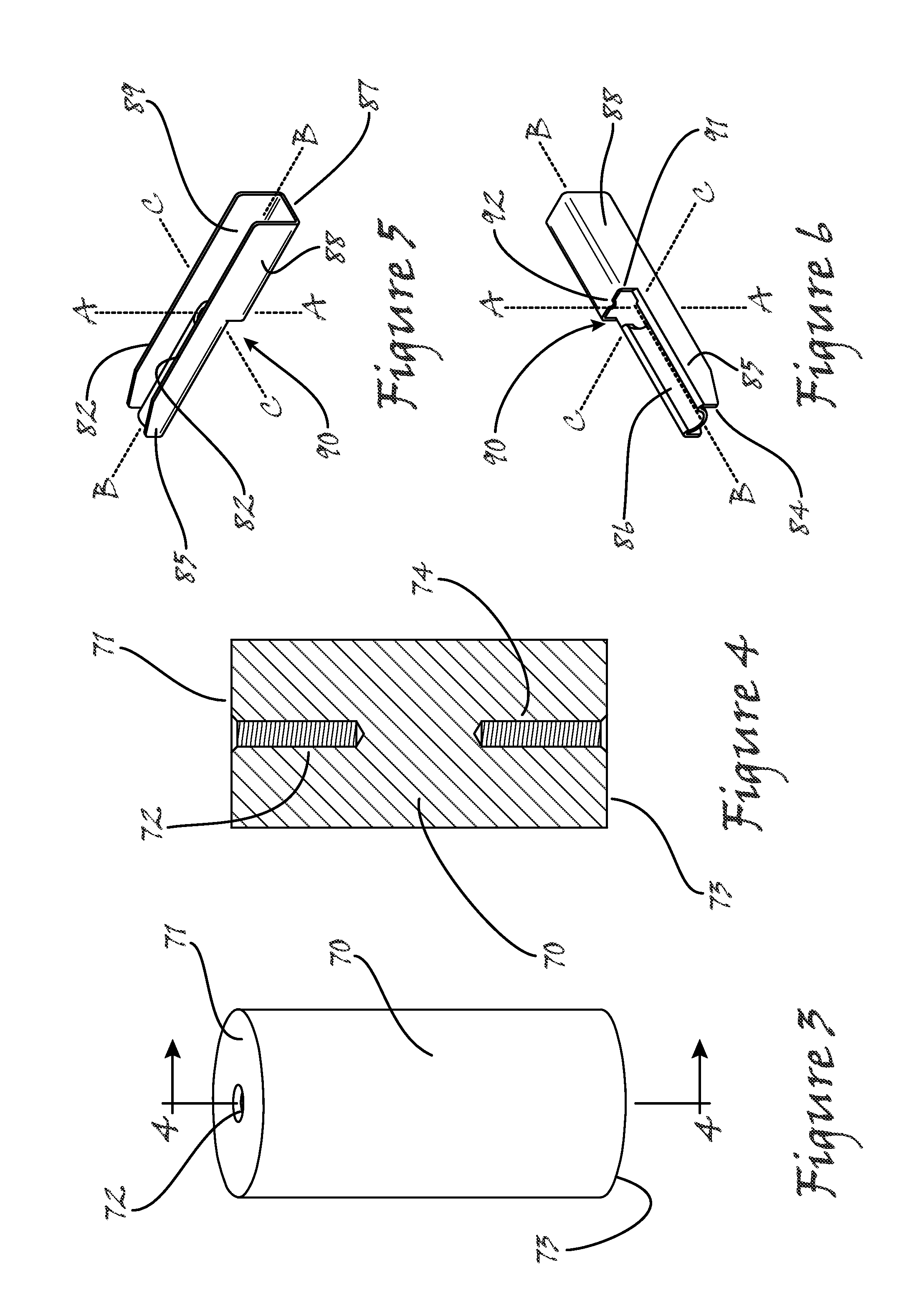
[0065]Referring now to the figures and to FIGS. 1 and 2 in particular, a first preferred implementation of the photovoltaic panel racking assembly 60 of the present invention is shown to generally comprise a generally cylindrically shaped standoff 70 cooperatively adjoined to a specially formed toggle 80 through an all thread rod 100 having positioned at an end opposite the standoff 70 a nut 101 that is sized and shaped to operatively engage with the toggle 80 as will be better understood further herein. In a critical aspect of the present invention, as will be bett...


PUM


Abstract

A photovoltaic panel racking assembly (60) includes a cylindrically shaped standoff (70) cooperatively adjoined to a specially formed toggle (80) through an all thread rod (100). A nut (101) is sized and shaped to operatively engage with the toggle (80) to fix the relative position of the toggle (80) and the nut (101). A rubber gasket (110) is provided in order to promote watertight sealing upon installation and during use of the racking assembly (60). A relief plate (112) may be provided in order to prevent installation damage to more generally fragile roofing materials such as asphalt shingles or like composite roofing (128). A rubber sleeve (102) is provided in order to facilitate positioning of the toggle (80) during installation of the racking assembly (60). Brackets (180, 200) are described for affixing one or more photovoltaic panels (170) to the racking assembly (60).

Description

RELATED APPLICATIONS[0001]This application claims all available benefit of and priority to P.C.T. international patent application No. PCT / US2011 / 059481 filed on Nov. 5, 2011 (designating the United States); U.S. provisional patent application Ser. No. 61 / 575,436 filed Aug. 22, 2011; U.S. provisional patent application Ser. No. 61 / 459,701 filed Dec. 17, 2010; and U.S. provisional patent application Ser. No. 61 / 456,330 filed Nov. 5, 2010. By this reference, the full disclosures, including the drawings, of P.C.T. international patent application No. PCT / US2011 / 059481; U.S. provisional patent application Ser. No. 61 / 575,436; U.S. provisional patent application Ser. No. 61 / 459,701; and U.S. provisional patent application Ser. No. 61 / 456,330 are incorporated herein as though now set forth in their respective entireties.FIELD OF THE INVENTION[0002]The present invention relates to building construction. More specifically, the present invention relates to a novel racking system for roof ins...

Claims


Application Information

Patent Timeline
Patent Type & Authority Applications(United States)
IPC IPC(8): H01L31/042
CPCH01L31/0422Y02E10/50Y02B10/12Y02B10/20H02S20/23F24J2/5245F24J2002/4667H02S20/00Y02E10/47F24S25/61F24S2025/6005Y02B10/10
Inventor SPONSELLER, GREGORY W.
Owner SPONSELLER GREGORY W
Why Eureka
Try Eureka