NANO smart glass system

Active Publication Date: 2013-09-19
WANG QI
View PDF7 Cites 115 Cited by
  • Summary
  • Abstract
  • Description
  • Claims
  • Application Information

AI Technical Summary

Benefits of technology

[0009]The main purpose of the present invention is to provide a new and improved nano smart glass system to intelligently adjust t

Problems solved by technology

There are some disadvantages about the PDLC and SPD glass such as:1. When the power is off, the glass is in the opaque sate.
In order to keep the glass transparent, the power must be always on, which will consume energy;In addition, when these types of glass are applied on the wi

Method used


Image

  • NANO smart glass system
  • NANO smart glass system
  • NANO smart glass system

Examples


Embodiment Construction

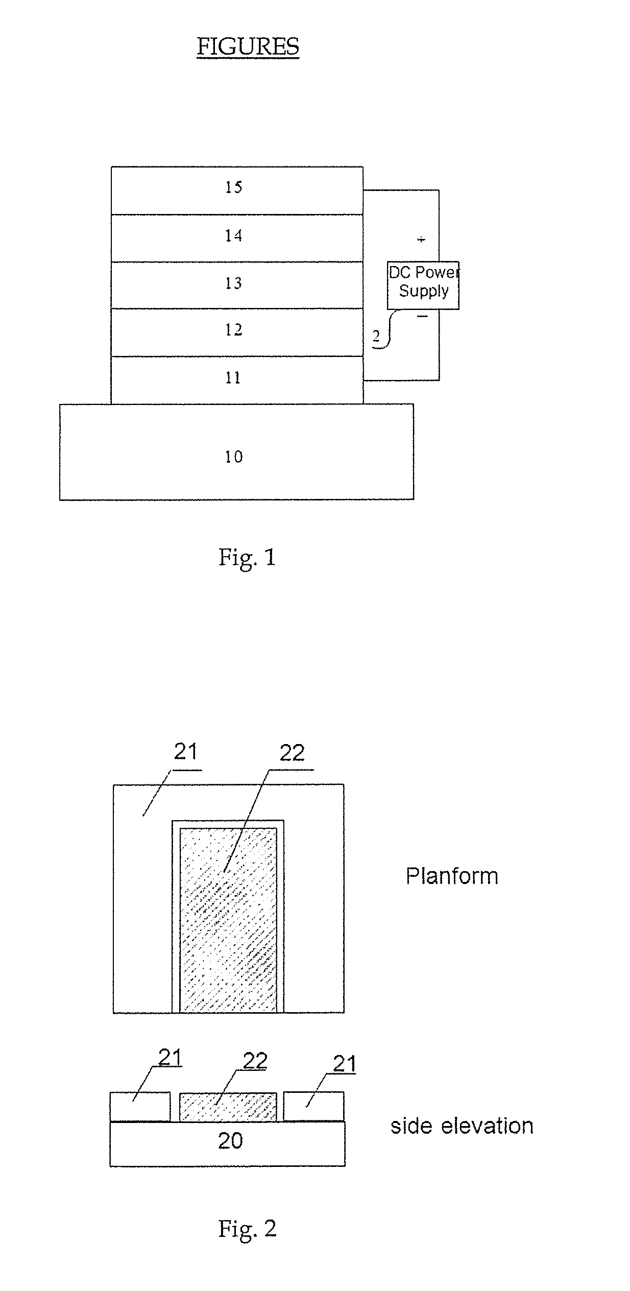
[0040]The present invention provides a nano smart glass system, including nano smart glass, the DC power supply, the sensor, and the control unit. Wherein, the nano smart glass includes glass and the electrochromic thin-film device.

[0041]As shown in FIG. 1, the electrochromic thin-film device consists of the order of at least one conductive cathode layer 11, at least one electrochromic layer 12, at least one ion conductive layer 13, at least one ion storage layer 14 and at least one conductive anode layer 15.

[0042]The total thickness of the electrochromic thin-film device is between 100-5000 nm.

[0043]The conductive cathode layer 11, the electrochromic layer 12, the ion conductive layer 13, the ion storage layer 14, and the conductive anode layer 15 are all thin films in nanometer scale, and the film materials are mainly the metal oxide, polymer materials or other chemical compounds; This thin-film device is transparent when the power is off.

[0044]The conductive cathode layer 11, the...


PUM


Abstract

The present invention provides a nano smart glass system, including nano smart glass, DC power supply, sensor, and control unit. Wherein, the nano smart glass includes glass and the electrochromic thin-film device; The anode of the DC power supply connects to the at least one conductive anode layer of the electrochromic thin-film device; the cathode of the DC power supply connects to the at least one conductive cathode layer of the electrochromic thin-film device; the DC power supply is used to provide 1V-50V DC voltage to the electrochromic thin-film device; the electrochromic thin-film device adheres to the inside surface of the glass through the at least one conductive cathode layer or the at least one conductive anode layer; The sensor measures outdoor or indoor conditions and send the real-time measurement data to the control unit. The control unit connects to the DC power supply, and it can control the output voltage of the DC power supply to the electrochromic thin-film device. The present invention can real-time and intelligently adjust the color of the glass, which can help saving energy and reducing green house gas emission.

Description

BACKGROUND OF THE INVENTION[0001]1. Field of the Invention[0002]This present invention relates to a kind of glass, especially to a kind of nano smart glass system.[0003]2. Description of the Prior Art[0004]Technologies for manufacturing glasses commonly known as “smart glass” technologies have currently been industrialized. The smart glasses are commonly manufactured as polymer dispersed liquid crystal (PDLC) glass, and suspended particle device (SPD) glass. The PDLC glass is manufactured by attaching a liquid crystal film similar to the material used in the LCD TV onto the glass while the SPD glass is manufactured with glass coated with a polymer film containing colloidal particles. In the power-off state, due to the light scattering caused by the random distribution of liquid crystal or colloidal particles, it results in the glass in the opaque state; while in the power-on state, the particles in the film are arranged in order so to allow the light passing through the film, so it ...

Claims


Application Information

Patent Timeline
IPC IPC(8): G02F1/163G02F1/153
CPCG02F1/163G02F1/1533E06B2009/2464
Inventor WANG, QI
Owner WANG QI
Why Eureka
Try Eureka