Three-dimensional shaping method and shaped object complex as well as three-dimensional shaping apparatus

a three-dimensional shaping and object technology, applied in the direction of dough shaping, additive manufacturing processes, manufacturing tools, etc., can solve the problems of affecting the appearance of the finished shaped object buried in the powder material, shaped objects tend to bump into each other, and the three-dimensional shaped object is unfortunately easy to break

Inactive Publication Date: 2013-09-19
CASIO COMPUTER CO LTD
View PDF4 Cites 41 Cited by
  • Summary
  • Abstract
  • Description
  • Claims
  • Application Information

AI Technical Summary

Benefits of technology

[0008]The present invention has been made in consideration of the above prior art, and has as its object to provide a three-dimensional shaping method, a shaped object complex, and a three-dimensional shaping apparatus, in which damage to the shaped objects can be inhibited, respectively.

Problems solved by technology

However, as the shaped object is buried into the stacked powder material and thus manufactured, the visibility of the completed shaped object buried in the powder material is low.
Particularly, if a plurality of shaped objects are simultaneously manufactured, the shaped objects tend to bump into each other when taken out from the powder material in which the shaped objects are buried.
Therefore, this three-dimensional shaped object is unfortunately easy to break, for example, when being formed or taken out.
Disadvantageously, this three-dimensional shaped object is thus unsuited for mass production.

Method used


Image

  • Three-dimensional shaping method and shaped object complex as well as three-dimensional shaping apparatus
  • Three-dimensional shaping method and shaped object complex as well as three-dimensional shaping apparatus
  • Three-dimensional shaping method and shaped object complex as well as three-dimensional shaping apparatus

Examples


first embodiment

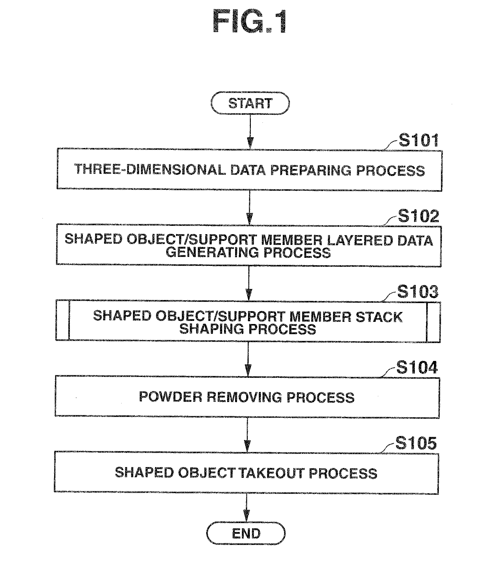
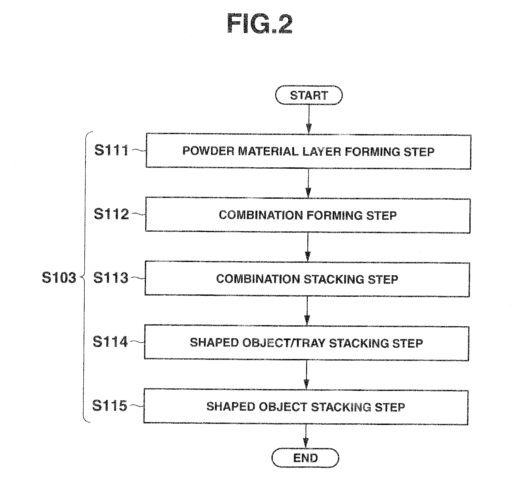
[0042]FIG. 1 is a flowchart showing the first embodiment of the three-dimensional shaping method according to the present invention. FIG. 2 is a flowchart showing an example of a shaped object / support member stack shaping process in the three-dimensional shaping method according to the present embodiment. FIG. 3A to FIG. 3E, FIG. 4A to FIG. 4D, FIG. 5A to FIG. 5C, and FIG. 6A and FIG. 6B are schematic process views showing how shaped objects and a tray (shaped object support member) are formed in the shaped object / support member stack shaping process according to the present embodiment. FIG. 7 is a schematic configuration diagram showing an example of the shaped objects and the tray that are formed by the shaped object / support member stack shaping process according to the present embodiment. Here, in FIG. 1, powder material layers are see-through, and the shaped objects and the tray are only shown for ease of explanation. FIGS. 8A and 8B are schematic process views showing how the s...

second embodiment

[0074]Now, the second embodiment of the three-dimensional shaping method according to the present invention is described.

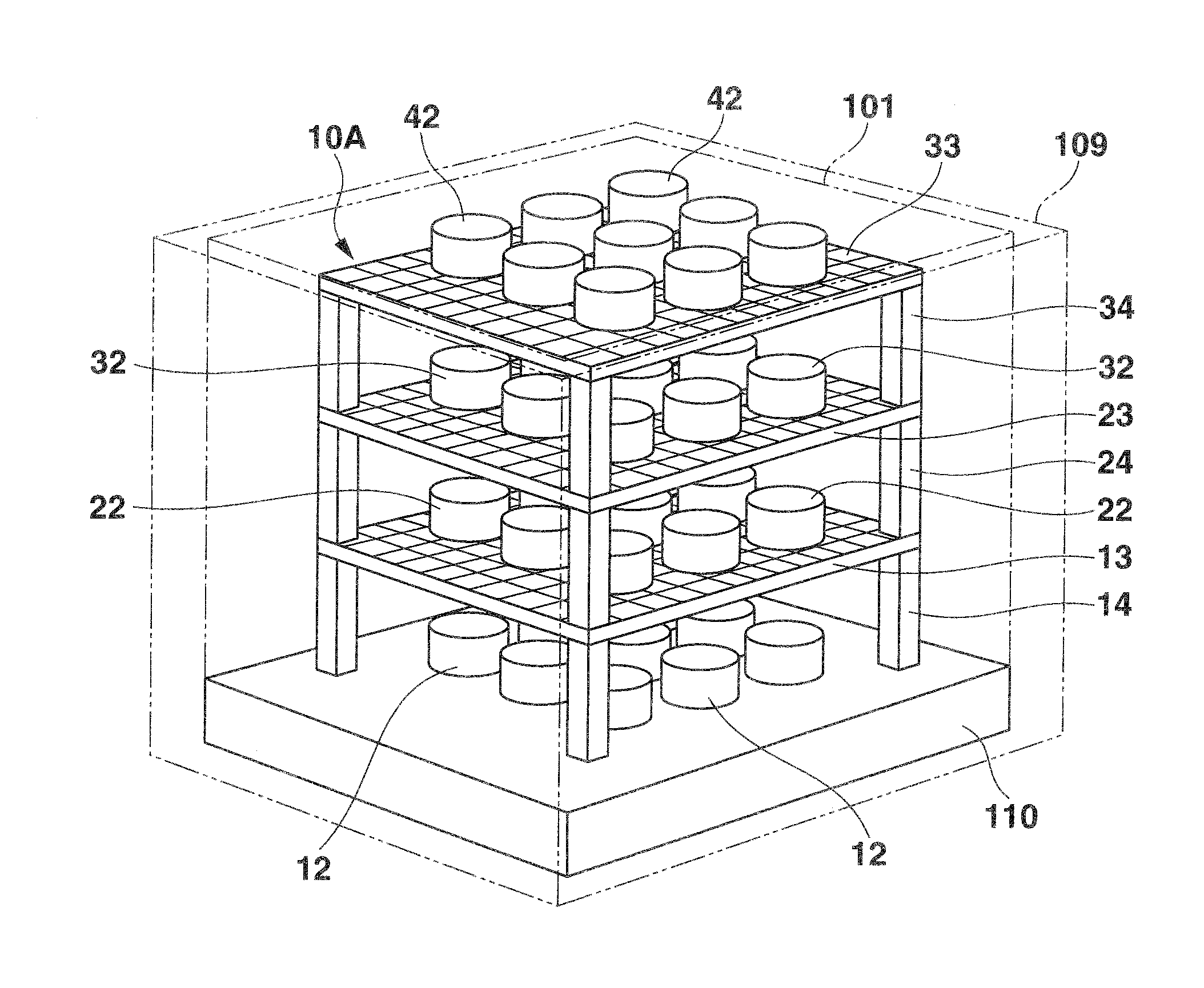
[0075]In the case described above according to the first embodiment, the tray 10A formed simultaneously with the shaped objects 12, 22, 32, and 42 has an integral configuration in which the tray bodies 13, 23, and 33 and the pillars 14, 24, and 34 of the respective stages are alternately stacked as shown in FIG. 7. In the second embodiment, the tray 10A is configured to be separable stage by stage.

[0076]FIG. 10A and FIG. 10B are schematic views showing one configuration example of shaped objects and a tray that are formed in the second embodiment of the three-dimensional shaping method according to the present invention. FIG. 10A is a schematic process view showing how the shaped objects and the tray are formed according to the present embodiment. FIG. 10B is a schematic configuration diagram showing an example of the tray of each stage (one stage) formed accordin...

third embodiment

[0089]Now, the third embodiment of the three-dimensional shaping method according to the present invention is described.

[0090]In the cases described above according to the first and second embodiments, the trays are formed on the respective stages for the shaped objects stacked and formed in stages, and the shaped objects are mounted on the trays (tray bodies), as shown in FIG. 7, FIG. 10A, and FIG. 10B. In the third embodiment, the adjacent shaped objects of the respective stages are linked to each other by a runner (shaped object support member) and stacked and formed in stages.

[0091]FIG. 12 is a flowchart showing an example of a shaped object / support member stack shaping process in the third embodiment of the three-dimensional shaping method according to the present invention. FIGS. 13A to 13D, FIG. 14A to FIG. 14C, and FIG. 15A and FIG. 15B are schematic process views showing how the shaped objects and a tray are formed in the shaped object / support member stack shaping process a...


PUM

PropertyMeasurementUnit
thicknessaaaaaaaaaa
flexibilityaaaaaaaaaa
chemical bindingaaaaaaaaaa

Abstract

A three-dimensional shaping method includes forming a combination to be each level of a three-dimensional shaped object and also forming a combination to be each level of a shaped object support member in each of a plurality of powder material layers having an uncured powder material in accordance with hierarchical shape data corresponding to each of the powder material layers.

Description

CROSS-REFERENCE TO RELATED APPLICATIONS[0001]This application is based upon and claims the benefit of priority from prior Japanese Patent Application No. 2012-052141, filed Mar. 8, 2012, the entire contents of which are incorporated herein by reference.BACKGROUND OF THE INVENTION[0002]1. Field of the Invention[0003]The present invention relates to a three-dimensional shaping method and a shaped, object complex as well as a three-dimensional shaping apparatus. More particularly, it relates to a three-dimensional shaping method to a form a three-dimensional shaped object (three-dimensional object) by using a powder stacking method, and a shaped object complex for use in the three-dimensional shaping method, as well as a three-dimensional shaping apparatus to conduct the three-dimensional shaping method.[0004]2. Description of the Related Art[0005]A three-dimensional stack shaping method is known as a method of forming (shaping) a three-dimensional shaped object. The three-dimensional ...

Claims


Application Information

Patent Timeline
Patent Type & Authority Applications(United States)
IPC IPC(8): B29C67/00B32B5/16
CPCB29C67/0074B29C67/0081B32B5/16B29C64/165B29C64/182Y10T428/31504
Inventor OSHIMA, KOUJI
Owner CASIO COMPUTER CO LTD
Why Eureka
Try Eureka