Method and Apparatus for Separating Individual Sealed Tubes from an Array of Tubes Sealed with a Membrane

a technology of sealing membrane and individual tubes, applied in the field of individual tubes from arrays of tubes, can solve the problems of insufficient sealing membrane, difficult sealing and separation of a large number of very small tubes, and the need for relatively complex equipment for automation of sealing and separation of large arrays of small tubes. the effect of increasing the tension in the sealing web

Active Publication Date: 2013-09-26
THE AUTOMATION PARTNERSHIP CAMBRIDGE
View PDF3 Cites 6 Cited by
  • Summary
  • Abstract
  • Description
  • Claims
  • Application Information

AI Technical Summary

Benefits of technology

[0034]Whereas the apparatus could work by supplying a series of sheets of sealing membrane to consecutive arrays of tubes, it would be operationally more efficient for the web of sealing membrane to be supplied from a continuous roll and for the sealing membrane transport mechanism to be configured to move the continuous web together with the storage rack during the transport of the storage rack from the sealing station to the punching station and, where the rack transport ass

Problems solved by technology

When the samples contained within the tubes are not subjected to frequent access, then a sealing membrane that is not resealable is sufficient.
As technology advances it is possible to process smaller samples and therefore there is a growing demand for smaller tubes, exacerbating these problems.
This has led to the situation where it is difficult to seal and separate a large number of very small

Method used


Image

  • Method and Apparatus for Separating Individual Sealed Tubes from an Array of Tubes Sealed with a Membrane
  • Method and Apparatus for Separating Individual Sealed Tubes from an Array of Tubes Sealed with a Membrane
  • Method and Apparatus for Separating Individual Sealed Tubes from an Array of Tubes Sealed with a Membrane

Examples


Embodiment Construction

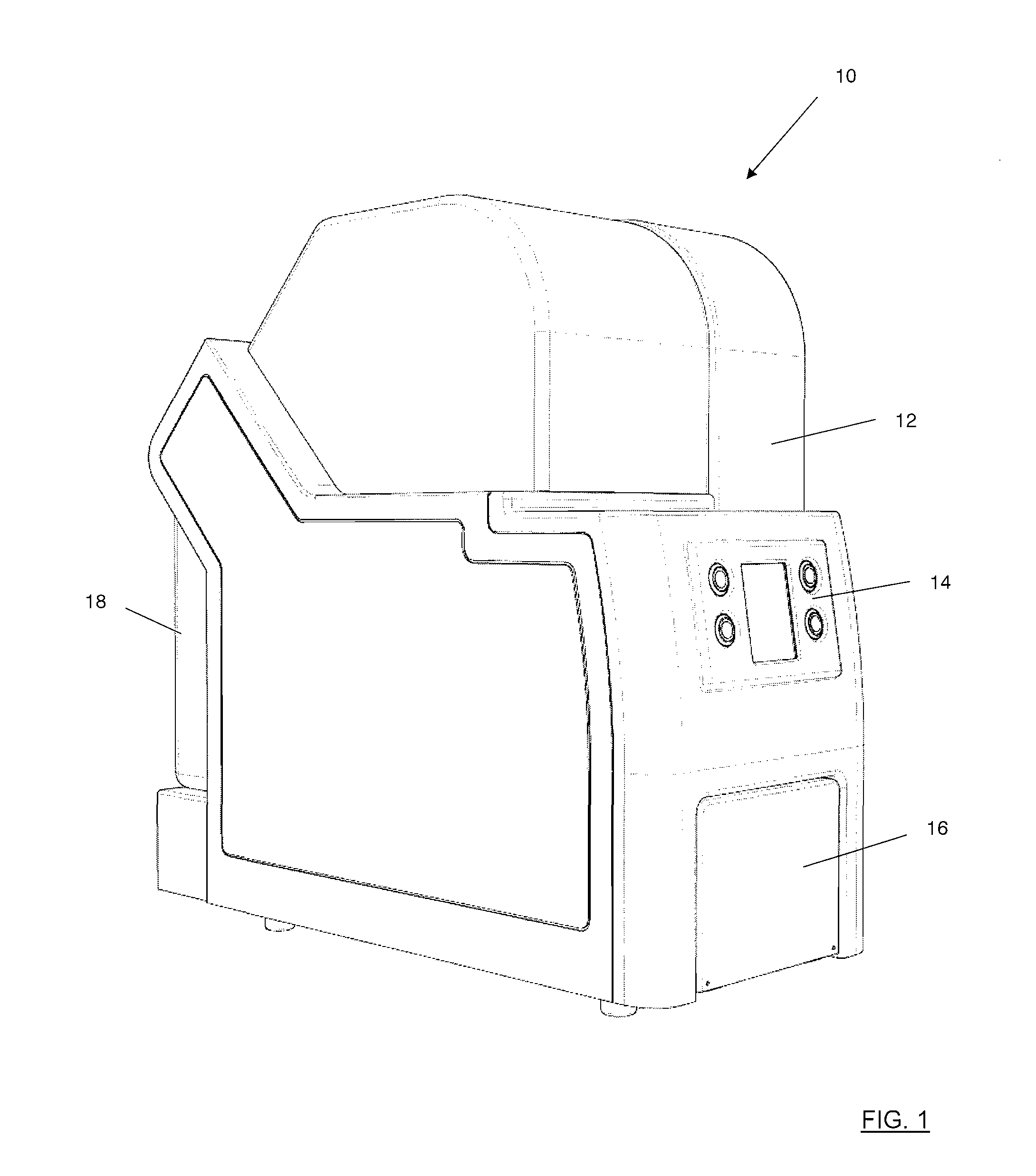
[0084]As shown in FIG. 1, an apparatus 10 for automated sealing and separation of an array of tubes comprises, generally, an outer cover 12 surrounding an interior. A control panel 14 is positioned on a front side of the apparatus for a user to control operation of the apparatus. A hinged hatch 16 on the front side provides access to the interior of the apparatus. A removable bin 18 is provided at the opposite, rear side of the apparatus.

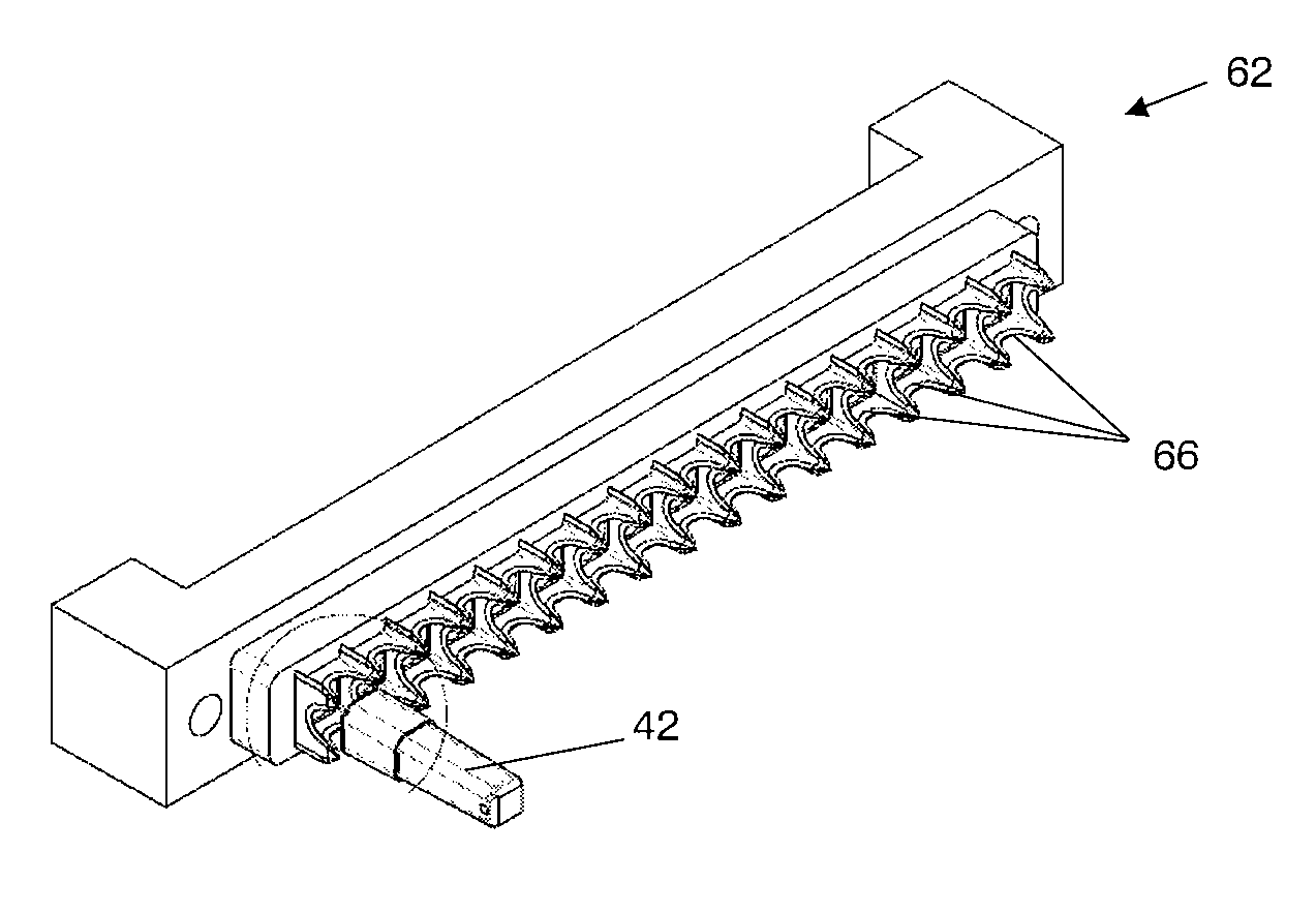
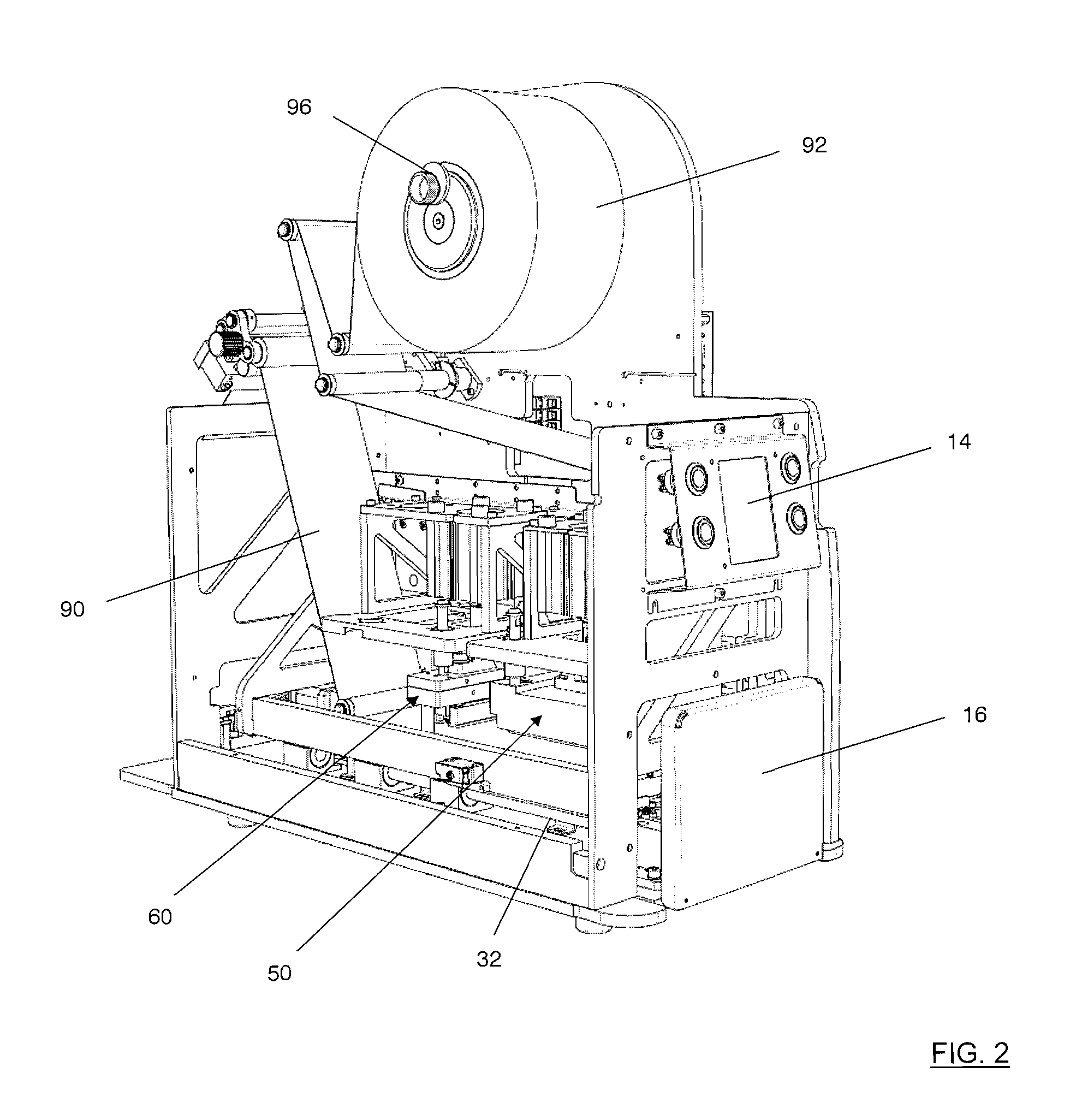
[0085]FIGS. 2 and 3 show the interior of the apparatus 10. In FIG. 3, the hatch 16 is hinged open, with a rack support 30 projecting out of the interior for loading and unloading of a storage rack 40 containing an array of tubes 42 in an x by y array. The storage rack 40 is mounted to the rack support 30 via a rack nest 44, with respective datum features provided to ensure proper alignment of the rack 40 with the support 30. The rack 40 may also be retained in the rack nest 44 with a clamp (not shown).

[0086]The rack support 30 comprises a carriage 3...


PUM

PropertyMeasurementUnit
Forceaaaaaaaaaa
Pressureaaaaaaaaaa

Abstract

Apparatus (10) for separating individual sealed tubes (42) from an array has rack support (30) for supporting an array of tubes with their upper rims (43) disposed in a horizontal plane and all sealed with a sealing membrane (90), and a punch station (60) comprising a punch tool (62) with cutting edge (66). Cutting edge (66) pierces through membrane (90) from above to separate an individual sealed tube (42) from the remainder of the membrane. The tool has multiple cutting edges (66) in a linear array corresponding to a column of a tightly-packed x by y array of tubes in the rack (40) to simultaneously separate the tubes (42) of a whole column. The cutting edge (66) starts piercing membrane (90) at the corners (43a) of each tube rim and progressively shears through the membrane. Ejector pins (68) retain the separated tubes within the rack (40).

Description

FIELD OF THE INVENTION[0001]The present invention relates generally to the separation of individual tubes from an array of tubes that have been sealed with a membrane, especially large arrays of small tubes.BACKGROUND TO THE INVENTION[0002]In biological and chemical assay processes and systems which operate with tubes containing samples of biological or chemical material it is important that the contents of the tubes remain isolated from the atmosphere in the lab and during storage so that the contents do not evaporate or become contaminated with foreign bodies. Therefore, it is common practice to seal tubes. This may be performed with a sealing membrane that, once punctured must be replaced, or it may be with a resealable membrane.[0003]When the samples contained within the tubes are not subjected to frequent access, then a sealing membrane that is not resealable is sufficient. The sealing membrane may take the form of a foil, backed with an adhesive that may be heat or pressure se...

Claims


Application Information

Patent Timeline
IPC IPC(8): B65B61/06B65B51/10
CPCB01L3/50853B65B61/065B65B51/10G01N2035/041B01L2300/044B01L2300/0672G01N35/0099B01L3/50855Y10T83/2133B01L3/5082B65B7/162B65B7/164B65B69/0033G01N35/02G01N35/028
Inventor OWEN, JUSTIN MICHAEL
Owner THE AUTOMATION PARTNERSHIP CAMBRIDGE
Why Eureka
Try Eureka