Exposure apparatus

a technology of exposure apparatus and laser beam, which is applied in the direction of microlithography exposure apparatus, printers, instruments, etc., can solve the problems of large apparatus, inability to effectively suppress the generation of speckles, and inability to contribute to image display. to achieve the effect of restricting brightness unevenness

Inactive Publication Date: 2013-09-26
DAI NIPPON PRINTING CO LTD
View PDF1 Cites 8 Cited by
  • Summary
  • Abstract
  • Description
  • Claims
  • Application Information

AI Technical Summary

Benefits of technology

[0011]The inventors have extensively researched under consideration of the points discussed above, and as a result, the inventors have contrived the invention regarding an exposure apparatus which illuminates a region repeatedly with coherent light beams that are diffracted by a hologram recording medium or the like and guides the illumination light to an exposure medium, to make speckles inconspicuous on the exposure medium. Moreover, the inventors have proceeded with researches and succeeded in improvement in the exposure apparatus to constantly prevent the generation of a region extremely bright in the region illuminated with coherent light beams which have been diffracted by a hologram recording medium and superimposed on one another on the region. Namely, the purpose of the present invention is to provide an exposure apparatus capable of making speckles inconspicuous on an optical image formed on an exposure medium and effectively suppressing the generation of brightness unevenness in a region illuminated with coherent light beams which have been diffracted by a hologram recording medium and superimposed on one another on the region.
[0018]According to the present invention, it is possible to make speckles inconspicuous effectively in a zone provided overlapping with a light modulator and on the surface of a photosensitive medium and also restrict brightness unevenness in the zone provided overlapping with the light modulator and on the surface of the photosensitive medium.

Problems solved by technology

Conventionally, several techniques for reducing speckles have been proposed, however, the techniques proposed so far cannot effectively and sufficiently suppress the generation of speckles.
Therefore, part of the laser beams is inevitably lost with no contribution to image display.
However, such a mechanical rotation mechanism becomes a relatively large apparatus, and power consumption is increased.
Moreover, even if the scattering plate is rotated, the position of the optical axis of an illumination light beam is not changed, hence it is impossible to sufficiently suppress the generation of speckles caused by the diffusion on a screen.
Moreover, speckles are not a problem unique to projection apparatuses but a problem to various apparatuses having an illumination device incorporated therein for illuminating an illumination zone with coherent light beams.
When speckles are generated due to light that illuminates an object to be read, it is impossible to read image information accurately.

Method used


Image

  • Exposure apparatus
  • Exposure apparatus
  • Exposure apparatus

Examples


first embodiment

[0031]An exposure apparatus according to a first embodiment of the present invention is capable of effectively preventing speckle, as a basic embodiment. Moreover, an exposure apparatus according to an applied embodiment of the present invention features an image forming module in addition to the configuration of the basic embodiment. Firstly, the basic embodiment of the present invention will be explained with reference to FIGS. 1 to 5.

Configuration of Basic Embodiment

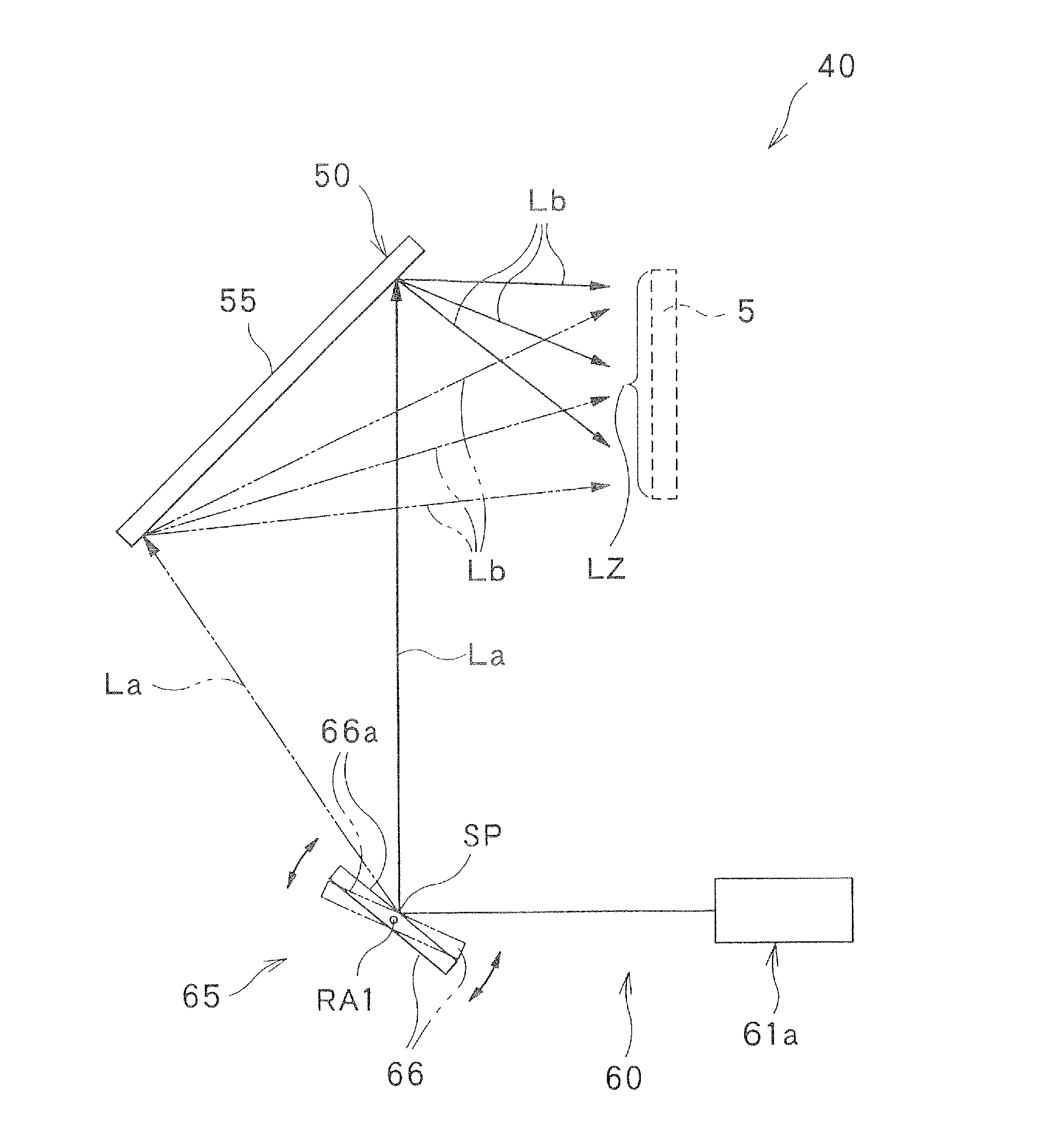
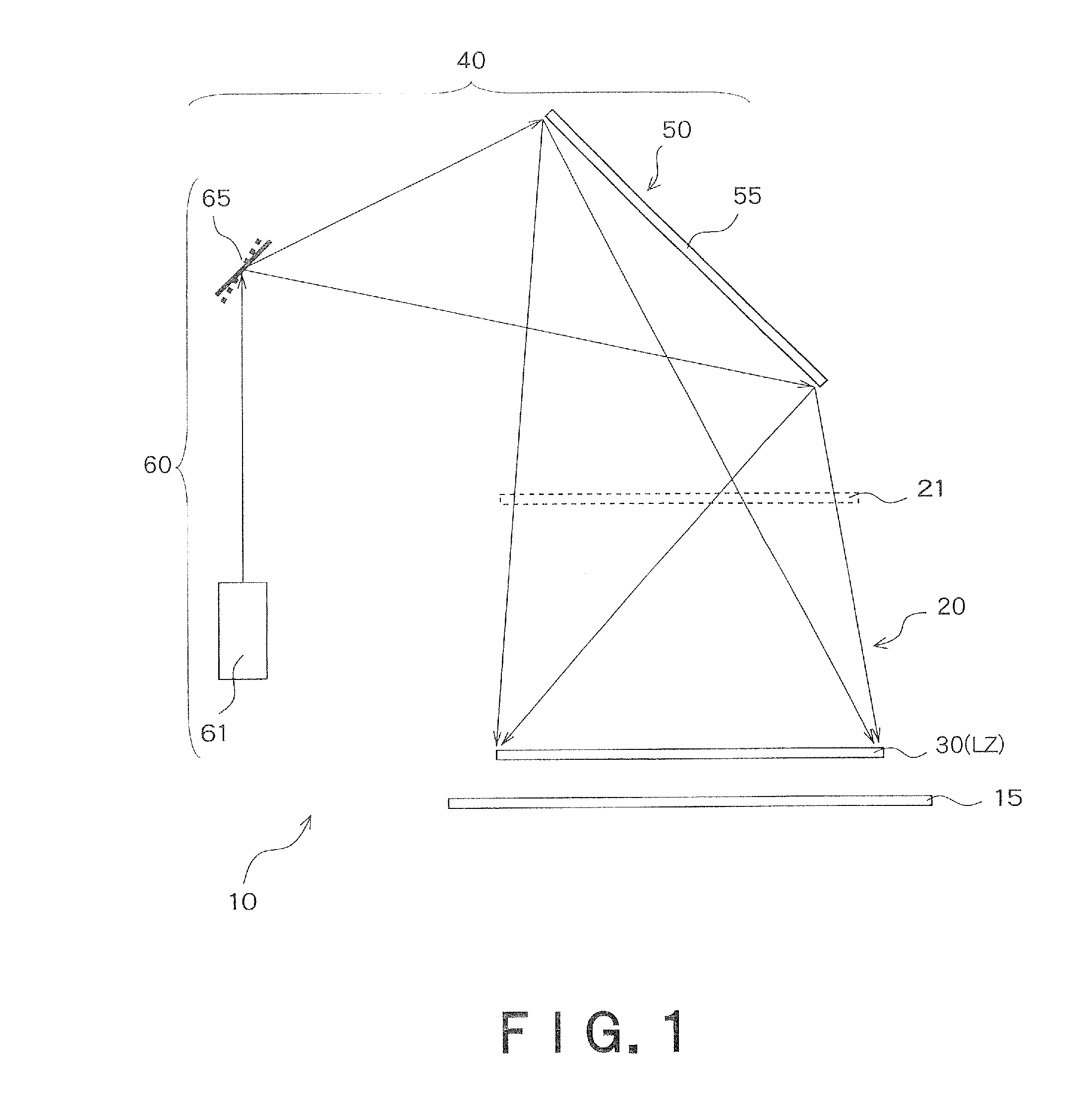
[0032]FIG. 1 is a view showing a schematic configuration of an exposure apparatus according to the basic embodiment of the present invention. An exposure apparatus 10 shown in FIG. 1 is provided with an optical device 50, an irradiation unit 60, and a spatial light modulator 30. Coherent light beams modulated by the spatial light modulator 30 are guided to the surface of the exposure medium 15. The optical device 50 and the irradiation unit 60 are included in an illumination device 40.

[0033]The optical device 50 has a...

applied embodiment

[0085]It is a precondition in the exposure apparatus of FIG. 1 that close exposure is performed without providing an image forming optical module between the spatial light modulator 30 and the exposure medium 15. In contrast, an applied embodiment which will be explained below has a feature in that an image forming (projection) optical module is provided.

[0086]FIG. 6 is a view showing a schematic configuration of an exposure apparatus according to an applied embodiment of the present invention. In FIG. 6, the components common with FIG. 1 are denoted by the same reference numerals, and different points will be mainly explained.

[0087]An exposure apparatus 10a of FIG. 6 is provided with, like FIG. 1, the optical device 50, the irradiation unit 60, and the spatial light modulator 30, and in addition, provided with an image forming module 25 disposed between the spatial light modulator 30 and the exposure medium 15, and a light diffusion device 21 disposed between the irradiation unit 6...

second embodiment

[0107]FIG. 8 is a view showing a schematic configuration of an exposure apparatus according to a second embodiment of the present invention. An exposure apparatus 10 of FIG. 8 is provided with an irradiation unit 60, an optical device 50, a first diaphragm 31, a condensing optical module 32, a spatial light modulator 30, and an image forming module 25, for exposing an image formed on the spatial light modulator 30 on an exposure member (exposure medium) 15. It is defined in FIG. 8 that the surface of the exposure member 15 is an X-Y plain and the axis orthogonal to the surface is a Z-axis.

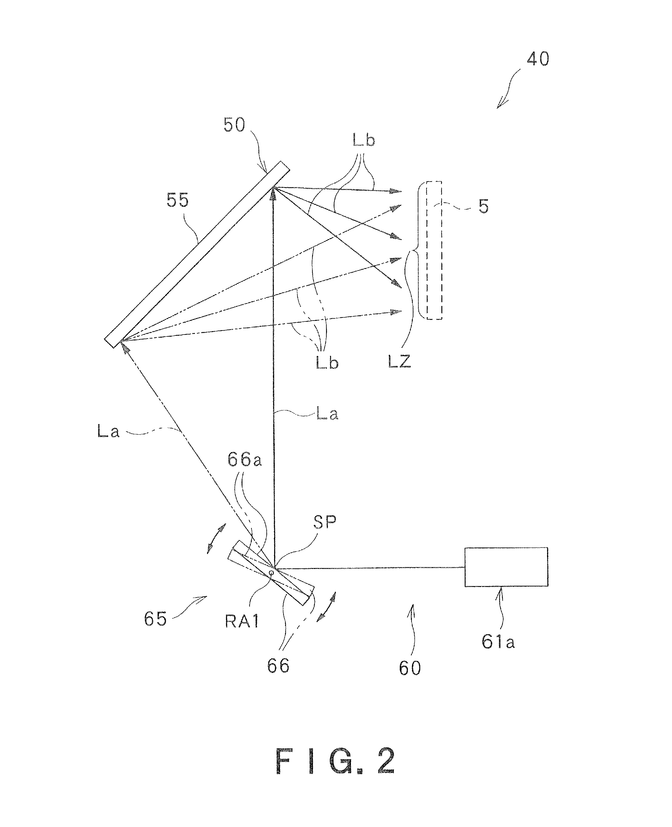
[0108]The irradiation unit 60 is an optical module for illuminating the optical device 50 as an illumination zone. The irradiation unit 60 illuminates the optical device 50 with illumination light beams Lb that are emitted in a direction varying with time, at a varying incident angle with respect to the effective area of the optical device 50. In this case, it is required that, by varying the direc...


PUM

PropertyMeasurementUnit
frequencyaaaaaaaaaa
diffusion angleaaaaaaaaaa
photosensitiveaaaaaaaaaa

Abstract

An exposure apparatus has an optical device configured to be capable of diffusing coherent light beams from respective points to the entire region of at least a specific zone, an irradiation unit configured to irradiate the coherent light beams to the optical device so that the coherent light beams scan a surface of the optical device, and a spatial light modulator that is provided at a location overlapped with the specific zone and illuminated by the illumination device. The irradiation unit makes the coherent light beams scan the surface of the optical device by changing propagation directions of the coherent light beams, and coherent light beams modulated by the spatial light modulator are guided to a surface of a photosensitive medium.

Description

TECHNICAL FIELD[0001]The present invention relates to an exposure apparatus that guides coherent light beams to the surface of an exposure medium.BACKGROUND ART[0002]Exposure apparatuses, for example, photolithography used for pattern formation for semiconductor devices have adopted a technique of transferring a reticle (mask) pattern onto a substrate such as a semiconductor wafer. In this technique, a photosensitive photoresist is applied on a substrate, a reticle is placed on the photoresist, and a high pressure mercury lamp, a metal halide lamp, etc. is provided above the reticle to illuminate the reticle, thereby a radiated light image corresponding to the reticle (mask) pattern being formed on the photoresist.[0003]Generally, in projection exposure apparatuses for example a stepper, a pattern to be transferred drawn on a reticle is projected onto a substrate via a projection optical module and formed thereon.[0004]However, high intensity discharge lamps such as high pressure me...

Claims


Application Information

Patent Timeline
Patent Type & Authority Applications(United States)
IPC IPC(8): G03F7/20
CPCG02B26/0816G02B27/48G03F7/70583G03F7/70291G03F7/70191
Inventor ISHIDA, KAZUTOSHIKURASHIGE, MAKIOTAKANOKURA, TOMOEOOYAGI, YASUYUKI
Owner DAI NIPPON PRINTING CO LTD
Why Eureka
Try Eureka