Radiator arrangement in a vehicle powered by a combustion engine

a technology of combustion engine and radiator, which is applied in the direction of indirect heat exchangers, lighting and heating apparatus, transportation and packaging, etc., can solve the problem that the engine is no longer viable as a cold source, and achieve the effect of reducing the temperature of the coolant and reducing the temperature of the contact surfa

Inactive Publication Date: 2013-10-03
SCANIA CV AB
View PDF3 Cites 5 Cited by
  • Summary
  • Abstract
  • Description
  • Claims
  • Application Information

AI Technical Summary

Benefits of technology

[0007]According to another preferred embodiment of the invention, the control unit is adapted to receiving information from a sensor which monitors a parameter related to the temperature of the engine, and to only circulating coolant through the line circuit if it receives information that the engine is at a lower temperature than a reference value. The reference value may be a predetermined temperature or a temperature which is related to that of the surrounding air. When the engine is used as cold source, it continuously receives thermal energy from the coolant circulating in the line circuit. The engine thus acquires a progressively rising temperature. When its temperature exceeds the reference value, the engine is no longer viable as a cold source. The control unit is with advantage adapted to circulating the coolant through an alternative line circuit in which the circulating coolant comes into heat-transferring contact with the condenser but not with the engine at times when the control unit receives information that the engine is at a higher temperature than the reference value. In the alternative line circuit some other cold source is used to cool the circulating coolant.
[0008]According to another preferred embodiment of the invention, the radiator arrangement comprises valve means which can be put into a first state in which they led the coolant through said line circuit, and a second state in which they lead the coolant through the alternative line circuit. Suitably located valve means may be used to divert the coolant relatively easily from circulation in the line circuit to circulation in the alternative line circuit. Such switching of the valve means takes place with advantage at times when the engine is at a temperature above the reference value. The alternative line circuit may comprise an air-cooled radiator for cooling the coolant, and the radiator arrangement comprises an electrically operated fan to force a cooling air flow through the radiator at times when the engine is at a temperature above said reference value. The electrically operated compressor may be an extra compressor

Problems solved by technology

When its temperature exceeds the reference value,

Method used


Image

  • Radiator arrangement in a vehicle powered by a combustion engine
  • Radiator arrangement in a vehicle powered by a combustion engine

Examples


Embodiment Construction

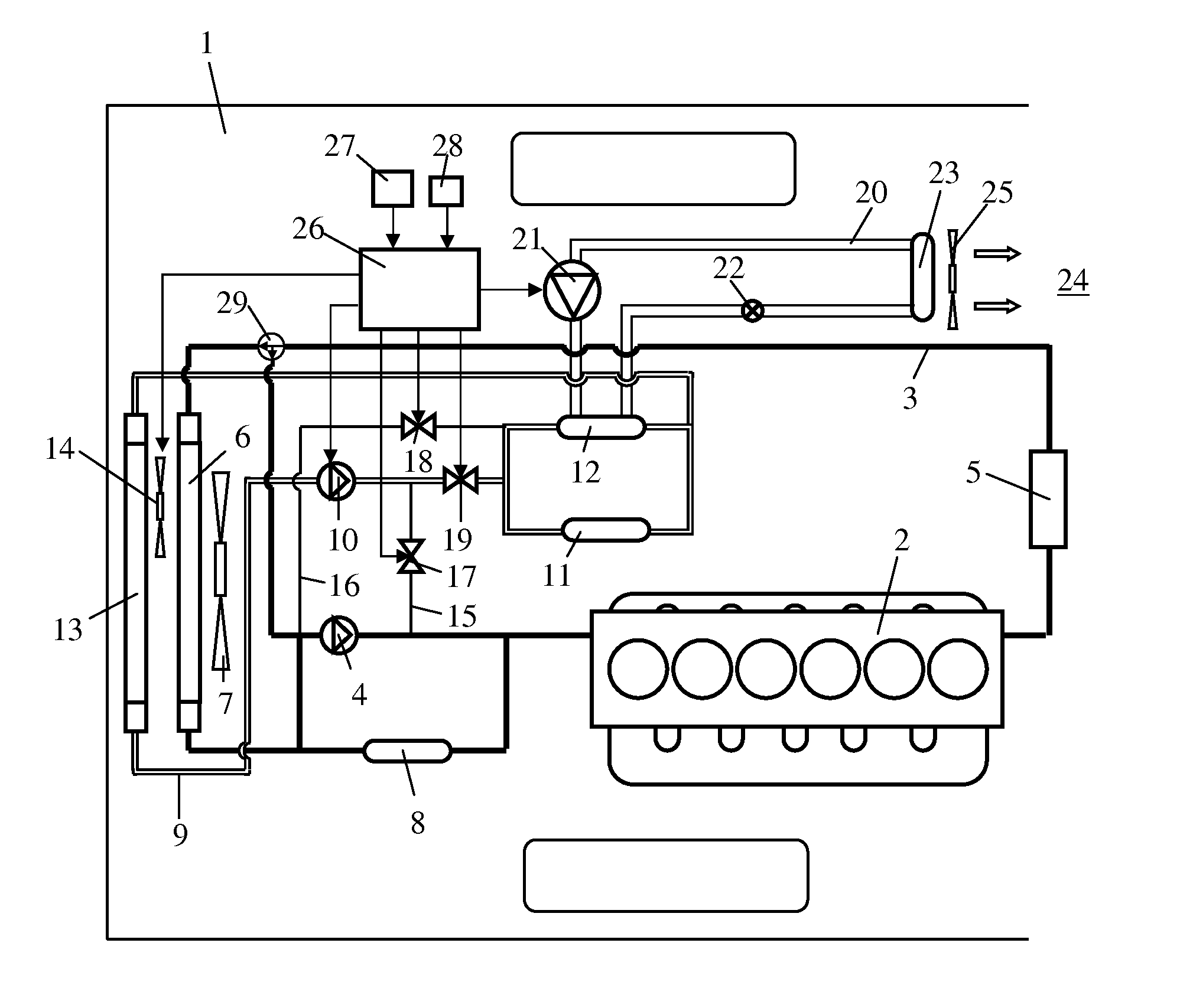
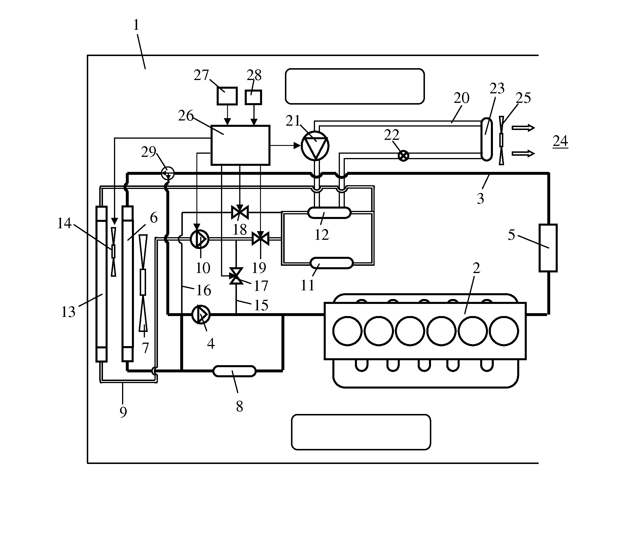
[0013]FIG. 1 depicts schematically a vehicle 1 powered by a combustion engine 2. The engine 2 may be a diesel engine and the vehicle 1 a heavy vehicle. During operation, the engine 2 is cooled by a first cooling system 3. The first cooling system 3 is hereinafter called the engine's cooling system. A first coolant pump 4 circulates the coolant through the engine's cooling system. The first coolant pump 4 may be driven by the engine 2. The first coolant pump 4 circulates the coolant initially through the engine 2. The coolant leaving the engine 2 is led in this case to an oil cooler 5 in which it cools oil which is used in a retarder. When the coolant has cooled the oil in the oil cooler 5, it is led to a thermostat 29. If the coolant is below an intended operating temperature, the thermostat 29 directs it to the coolant pump 4. When the coolant is above the intended operating temperature, it is led to an air-cooled first radiator 6 fitted at a forward portion of the vehicle 1. The c...


PUM


Abstract

A radiator arrangement in a vehicle (1) powered by a combustion engine (2). The arrangement includes an AC system (20) with a circulating refrigerant which gives off heat in a condenser (12) and absorbs heat in an evaporator (23) and the evaporator is in contact with air close to a cab space (24) in the vehicle (1). A line circuit in which circulating coolant comes into heat-transferring contact with the engine (2). The condenser (12) is in heat-transferring contact with coolant which circulates through the line circuit. An activator for the AC system (20) causes coolant to be circulated through the line circuit when the engine (2) is not in operation. When the engine (2) is cold, coolant in the line circuit delivers thermal energy it acquires in the condenser (12).

Description

BACKGROUND TO THE INVENTION AND PRIOR ART[0001]The present invention relates to a radiator arrangement in a vehicle powered by a combustion engine according to the preamble of claim 1.[0002]An AC system is commonly used to cool the cab space in a vehicle. AC systems comprise a cooling circuit with a circulating refrigerant. The circulating refrigerant cools the air in the cab space when it vaporises in an evaporator and gives off heat to surrounding air when it condenses in a condenser. The condenser is usually situated at the front portion of the vehicle near to the radiator in which the coolant in the engine's cooling system is cooled. During operation, air is drawn through the condenser and the radiator by a radiator fan driven by the engine. The engine also drives a compressor which compresses and circulates the refrigerant in the AC system.[0003]It is often desired to use the AC system in the vehicle even at times when the engine is not running. A known practice in this respect...

Claims


Application Information

Patent Timeline
IPC IPC(8): B60H1/32
CPCB60H1/3205B60H1/3227B60H1/32B60H1/00F28D1/00B60H1/00271B60H1/3204B60H2001/3289B60H2001/3266
Inventor KARDOS, ZOLTANHALL, OLA
Owner SCANIA CV AB
Why Eureka
Try Eureka