Metal-stamping die manufactured by additive manufacturing

a metal stamping die and additive manufacturing technology, applied in the field of sheet metal forming tools, can solve the problems of low complexity tools, difficult, if not impossible, parts are disadvantageously manufactured with multiple tools, etc., and achieve the effect of reducing the number of die tools and quick and inexpensive design

Inactive Publication Date: 2013-10-03
A RAYMOND & CO
View PDF23 Cites 35 Cited by
  • Summary
  • Abstract
  • Description
  • Claims
  • Application Information

AI Technical Summary

Benefits of technology

[0006]The present apparatus and method for making a metal-stamping die is advantageous over traditional methods. For example, the present apparatus and method advantageously merges multiple die tools into a single die configuration that would otherwise be prohibitively expensive, if not impossible, to produce as a conventional die. Furthermore, reducing the number of die tools results in a savings of thousands of dollars and many weeks of die manufacturing time. In other aspects, the present method allows for quick and inexpensive design and part revisions from one manufacturing cycle to another. In yet another aspect, the present method provides a temporary tool for use while a production tool is being built or repaired. The additive manufacturing process also creates surfaces, internal voids and other die formations that would be very difficult, if not impossible, to manufacture with conventional milling machines, electrical discharge machines (EDM), and the like. Additional advantages or features of the present invention can be found in the following description and appended claims as well as in the accompanying drawings.

Problems solved by technology

Typically for low volume part manufacturing, such as in prototype processing, parts are disadvantageously manufactured with multiple, low complexity tools due to the time and cost required for tool modification at each design stage.
The additive manufacturing process also creates surfaces, internal voids and other die formations that would be very difficult, if not impossible, to manufacture with conventional milling machines, electrical discharge machines (EDM), and the like.

Method used


Image

  • Metal-stamping die manufactured by additive manufacturing
  • Metal-stamping die manufactured by additive manufacturing
  • Metal-stamping die manufactured by additive manufacturing

Examples


Embodiment Construction

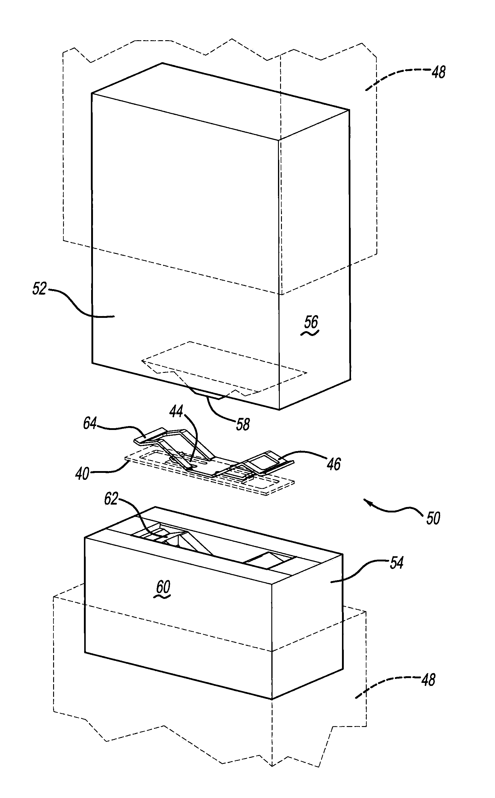
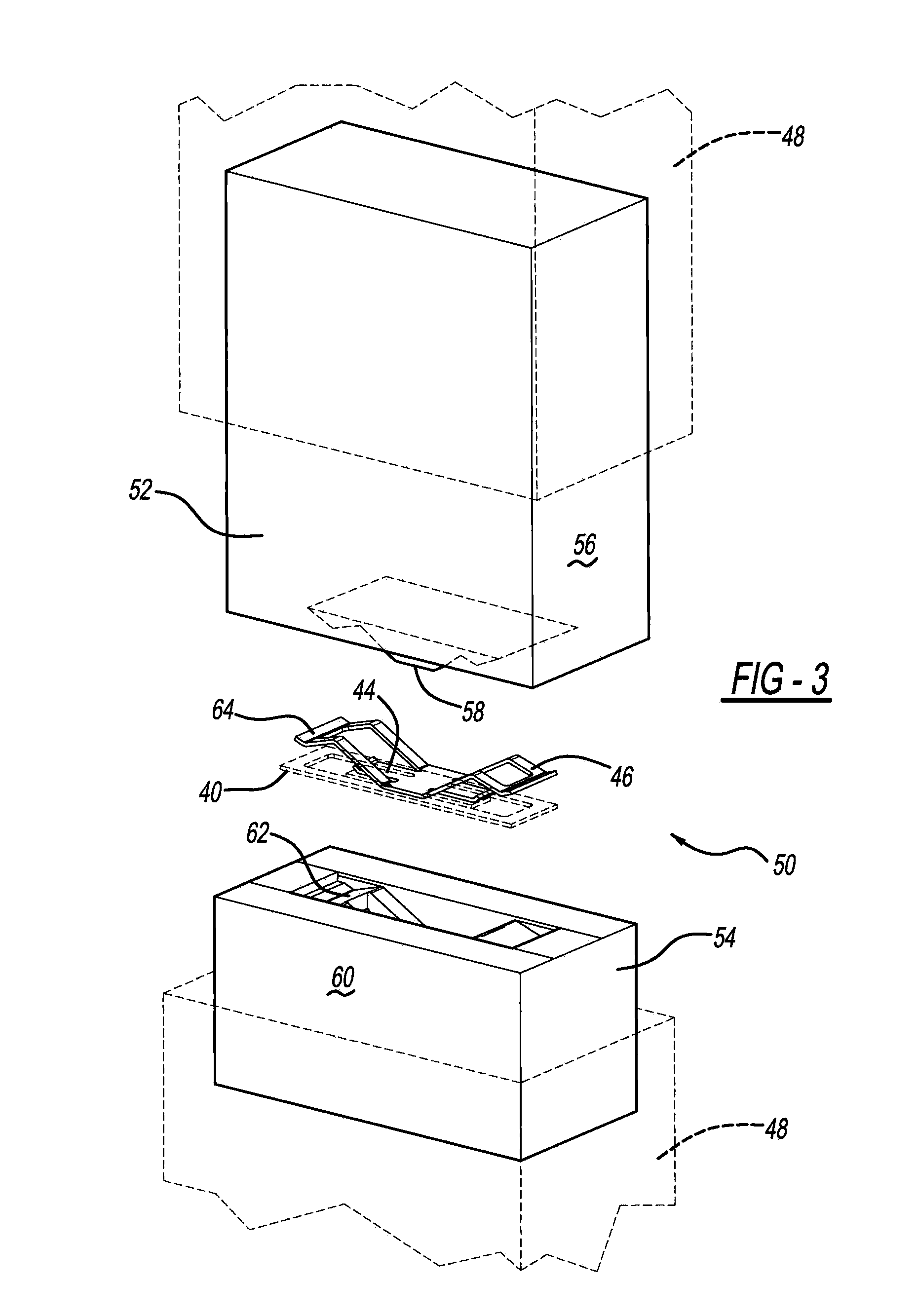
[0020]A metal-stamping die, in other words a die for stamping sheet metal parts, is made by an additive manufacturing process, such as three-dimensional printing (“3DP”). The die is preferably used to stamp sheet metal fasteners, such as, but not being limited to snap-in clips.

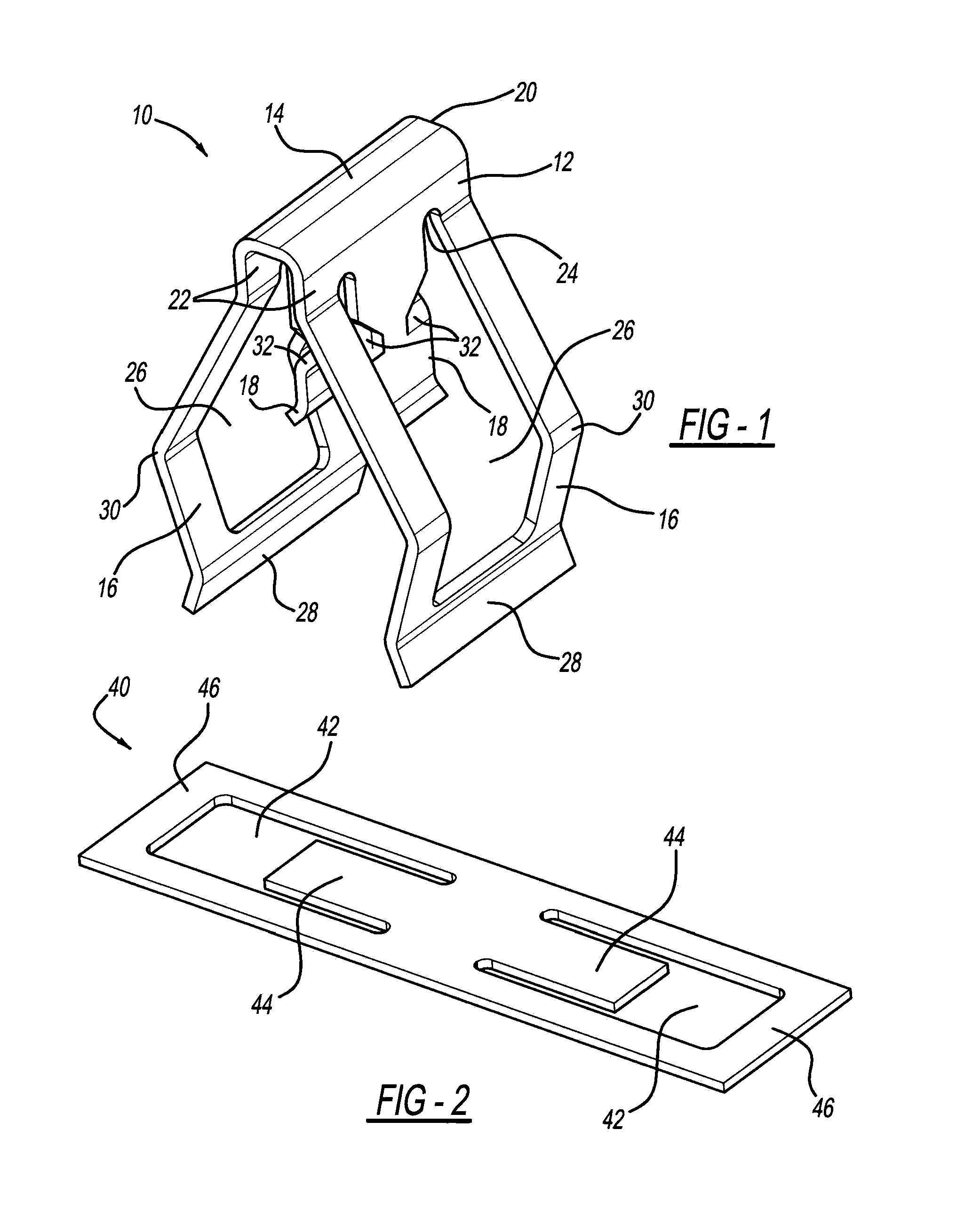
[0021]In a preferred embodiment, a part manufactured by the stamping process of the present invention is a trim fastener or clip 10, as illustrated in FIG. 1. Trim clip 10 can be employed in an automotive vehicle to connect two panels together, for example, by pushing onto a stud or clip tower in one panel and snapping into a hole in a vehicular body panel. Although the part is depicted as trim clip 10, it should be understood that a myriad of other parts can be manufactured with the stamping process and tooling of the present invention. For example, stamped parts formed with the tooling of the present invention may be employed in other industrial or residential settings, such as with solar panels, HVAC system...


PUM

PropertyMeasurementUnit
thicknessaaaaaaaaaa
thicknessaaaaaaaaaa
thickaaaaaaaaaa

Abstract

A metal-stamping die or tool is provided. Another aspect uses an additive manufacturing machine and material to create a die. A further aspect provides a method of making a die from an additive manufacturing process and/or using such a die to stamp a metal part, such as a fastener or clip.

Description

CROSS REFERENCE TO RELATED APPLICATION[0001]This application claims the benefit and priority of U.S. Provisional Application Ser. No. 61 / 617,274 filed Mar. 29, 2012, which is incorporated by reference herein.BACKGROUND AND SUMMARY[0002]The present disclosure relates generally to sheet metal forming tools and more particularly to manufacturing of metal-stamping dies using additive manufacturing processes.[0003]Stamped metal parts are typically manufactured by pressing sheet metal between upper and lower machined steel dies to form a closed cavity in the net shape of a final part. Depending on part complexity, the desired net shape may be achieved in a single stage operation or through multiple stamping stages. Accordingly, a single tool having a complex profile or multiple sets of low complexity tools may alternately be used to produce the desired net shape for the stamped part. Exemplary stamping processes are disclosed in U.S. Pat. No. 2,372,516 entitled “Machine for Forming Materi...

Claims


Application Information

Patent Timeline
Patent Type & Authority Applications(United States)
IPC IPC(8): B29C67/00B21D22/02
CPCB29C67/0062B21D22/02B21D37/20B29C67/0059B21D37/01B29C67/0051B29C64/112B33Y80/00B33Y10/00
Inventor DANBY, MICHAEL RICHARDREZNAR, JASON F.
Owner A RAYMOND & CO
Why Eureka
Try Eureka