Control apparatus for internal combustion engine

a control apparatus and internal combustion engine technology, applied in the direction of electric control, machines/engines, liquid fuel feeders, etc., can solve the problems of low temperature inside the intake pipe and the temperature of the intake port wall surface, and the negative pressure is not yet generated inside the intake pipe, so as to reduce the amount of unburned hc discharged into the atmosphere at start-up. , the effect of reducing the amount of unburn

Active Publication Date: 2013-10-03
TOYOTA JIDOSHA KK
View PDF9 Cites 5 Cited by
  • Summary
  • Abstract
  • Description
  • Claims
  • Application Information

AI Technical Summary

Benefits of technology

[0026]According to the first invention, by controlling a timing at which to start to supply fuel to a delayed cylinder based on predetermined parameters including a representative temperature of the internal combustion engine, the amount of unburned HC that is discharged into the atmosphere from an end (tailpipe) of an exhaust passage at start-up can be reliably reduced.
[0027]According to the second invention, it is possible to reliably prevent a state in which there are large vibrations in an internal combustion engine from continuing for a long time at start-up.
[0028]According to the third invention, prevention of a state in which large vibrations in an internal combustion engine continue for a long time at start-up, and a reduction in the amount of unburned HC that is discharged into the atmosphere at start-up can both be more reliably achieved.
[0029]According to the fourth invention, in an internal combustion engine that is capable of using a fuel containing alcohol, the above effects can be reliably obtained even when fuels of various alcohol concentrations are used.
[0030]According to the fifth invention, the amount of unburned HC that is discharged into the atmosphere at start-up can be reduced more reliably.

Problems solved by technology

However, when starting an internal combustion engine, particularly at cold start-up, the temperature inside the intake pipe and the temperature of the intake port wall surface are low, and furthermore, a negative pressure is not yet generated inside the intake pipe.
However, when a large quantity of fuel is supplied, a proportionately large amount of unburned hydrocarbon (HC) is discharged to an exhaust passage from inside the respective cylinders.

Method used


Image

  • Control apparatus for internal combustion engine
  • Control apparatus for internal combustion engine
  • Control apparatus for internal combustion engine

Examples


embodiment 1

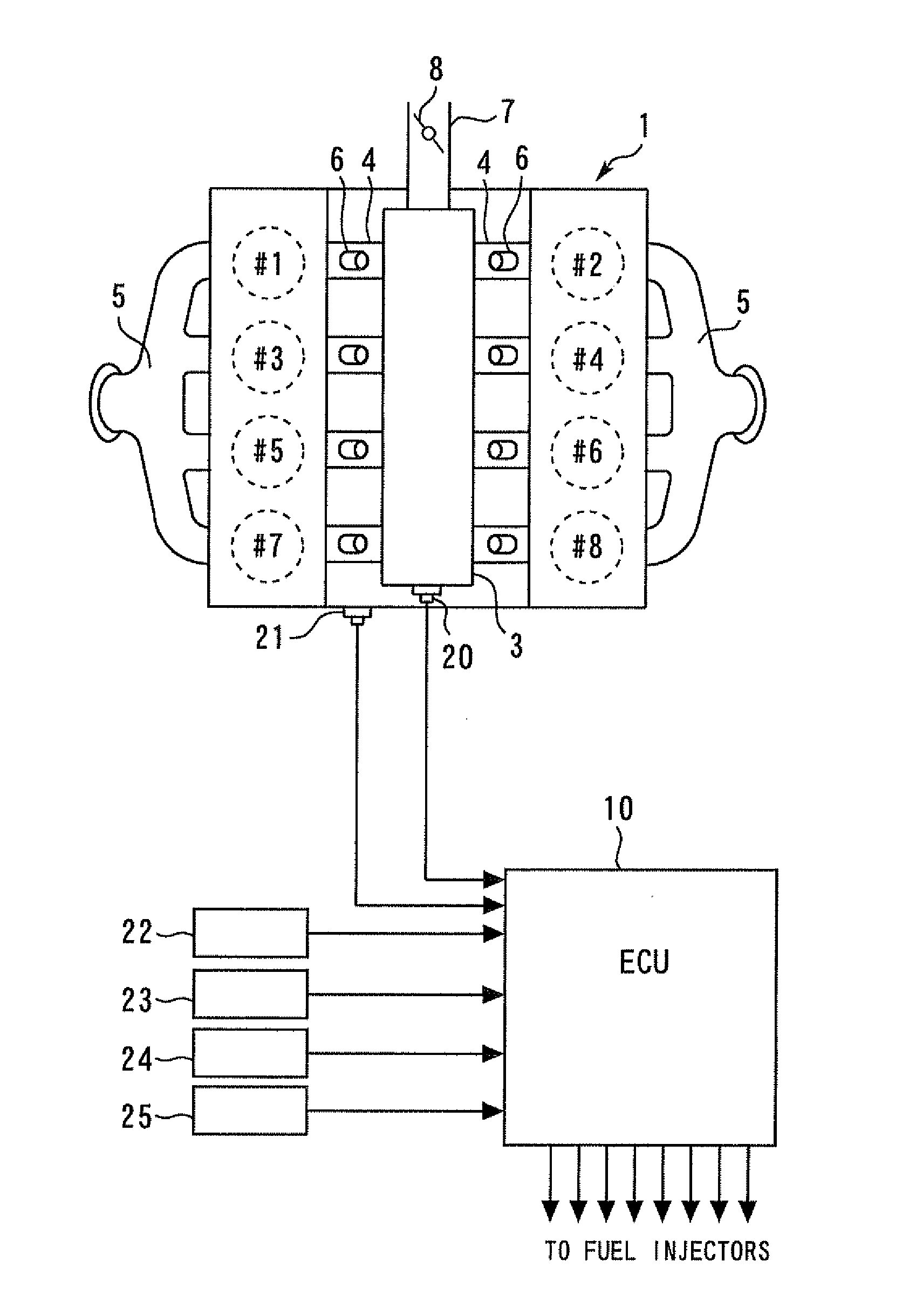
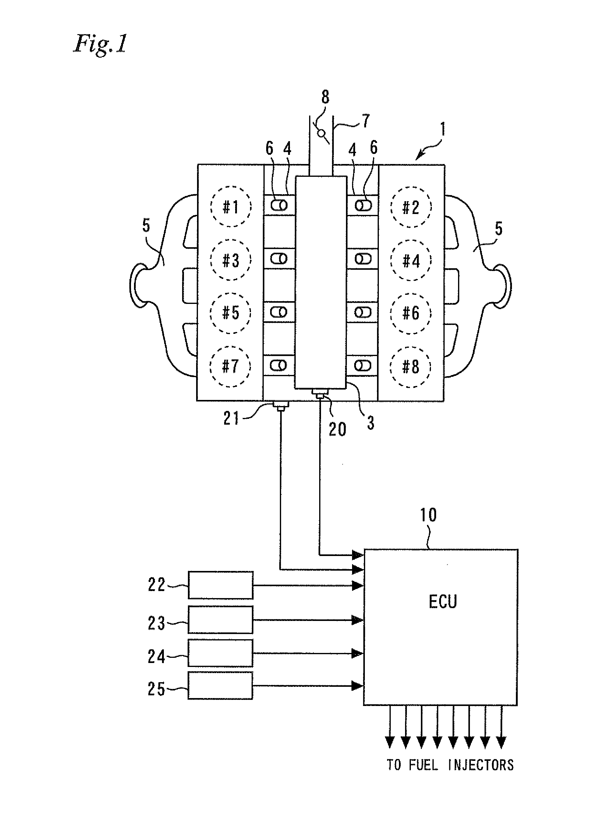
[0044]FIG. 1 is a view for describing the system configuration of Embodiment 1 of the present invention. As shown in FIG. 1, the system of the present embodiment includes an internal combustion engine 1 (hereunder, referred to simply as “engine”). The engine 1 is a V8 four-stroke reciprocating engine that has eight cylinders. In the following description, the numbers of the respective cylinders are denoted by reference numerals #1 to #8. The engine 1 is a spark-ignition engine that includes a spark plug (unshown) for each cylinder. The engine 1 is capable of operating using 100% gasoline as a fuel, and is also capable of operating using an alcohol-containing fuel in which gasoline and an alcohol (ethanol, methanol or the like) are mixed. Note that the number of cylinders and the cylinder arrangement of an engine according to the present invention are not limited to that of a V8 engine. For example, the engine may be an in-line six-cylinder engine, a V6 engine, a V10 engine, or a V12...

embodiment 2

[0073]Next, Embodiment 2 of the present invention is described referring to FIG. 9 and FIG. 10. The description of Embodiment 2 centers on differences with respect to the foregoing Embodiment 1, and a description of like items is simplified or omitted.

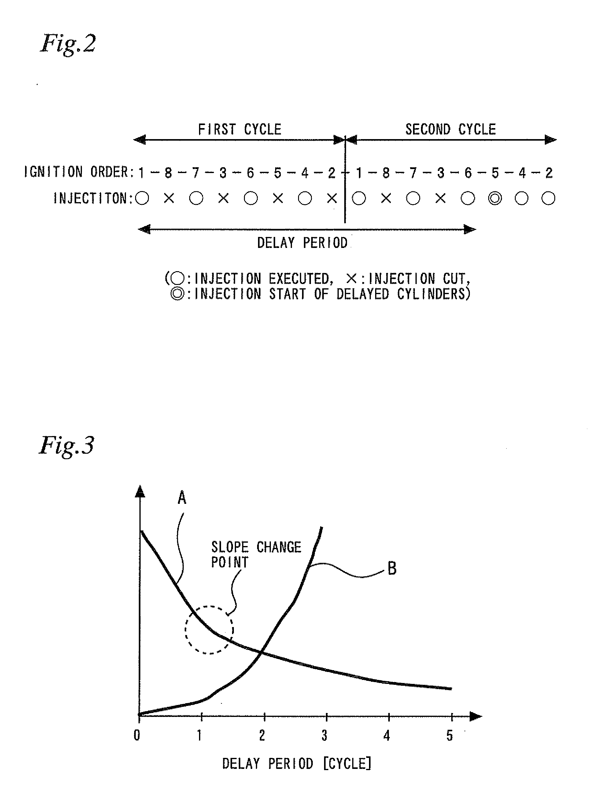
[0074]According to the control of the above described Embodiment 1, since the ECU 10 performs control so that the starting engine speed becomes equal to or greater than the target engine speed α, the slower that the rate of increase in the engine speed is, the longer the delay period becomes. Since only some of the cylinders perform combustion during the delay period, the combustion intervals are longer that when the engine 1 is operating on all cylinders. As a result, in comparison to when the engine 1 is operating on all cylinders, rotational fluctuations increase and the engine 1 is liable to vibrate more. Consequently, if the delay period is too long, a state in which there are large vibrations continues for a long time, and this i...

embodiment 3

[0083]Next, Embodiment 3 of the present invention is described referring to FIG. 11. The description of Embodiment 3 centers on differences with respect to the above described embodiments, and a description of like items is simplified or omitted.

[0084]FIG. 11 is a view for describing the configuration of an exhaust system of the engine 1 of the present embodiment. As shown in FIG. 11, according to the present embodiment, on the bank on the left side in the figure, cylinders #1 and #7 share an exhaust manifold 51, and cylinders #3 and #5 share an exhaust manifold 52. The exhaust manifolds 51 and 52 are connected to an exhaust gas purification catalyst 31. On the bank on the right side in FIG. 11, cylinders #2 and #8 share an exhaust manifold 53, and cylinders #4 and #6 share an exhaust manifold 54. The exhaust manifolds 53 and 54 are connected to an exhaust gas purification catalyst 32. A comparison of the surface areas (outer surface area) of the respective exhaust manifolds 51 to 5...


PUM


Abstract

A control apparatus for an internal combustion engine that can suppress the emission of unburned HC accompanying start-up of an internal combustion engine. The control apparatus including a fuel supply control unit that initially supplies fuel to only some cylinders, and delays the start of fuel supply to delayed cylinders that are cylinders other than the aforementioned cylinders; an engine discharge gas HC amount predicting unit that calculates a relationship between a delayed cylinder starting engine speed that is a engine speed at a timing at which a cycle starts in which a delayed cylinder initially carries out combustion and a predicted value of an engine discharge gas HC amount; and a target engine speed calculating unit that calculates a target engine speed that is a target value of the delayed cylinder starting engine speed.

Description

DESCRIPTION[0001]1. Technical Field[0002]The present invention relates to a control apparatus for an internal combustion engine.[0003]2. Background Art[0004]In an internal combustion engine, although a part of fuel that is injected into an intake port from a fuel injector vaporizes in the state it is in when it is injected, the remainder adheres temporarily to a wall surface (including an intake valve; the same applies hereunder) of the intake port. The fuel that adheres to the intake port is evaporated by a negative pressure inside an intake pipe or the action of heat from the intake port wall surface, and forms an air-fuel mixture together with a vaporized part of fuel that has been newly injected from the fuel injector. At a time of steady operation, there is a balance between the amount of fuel that is injected from the fuel injector and adheres to the intake port, and the amount of fuel that has been adhered to the intake port that vaporizes. Therefore, by injecting a fuel amou...

Claims


Application Information

Patent Timeline
Patent Type & Authority Applications(United States)
IPC IPC(8): F02D41/00
CPCF02D17/02F02D41/0087F02D41/062F02D41/1459F02D41/1497F02D2200/021F02D2200/0611F02D2200/101F02D41/00F02D41/0025
Inventor ASO, KOJITANAKA, HIROSHI
Owner TOYOTA JIDOSHA KK
Why Eureka
Try Eureka