
Internal combustion engine with improved tank cleaning

a technology of internal combustion engine and tank cleaning, which is applied in the direction of fuel injection apparatus, non-fuel substance addition to fuel, charge feed system, etc., can solve the problems of reduced time in which a sufficient vacuum is available, and complex methods, and achieve good cleaning of the fuel vapor store , the effect of low cos

Inactive Publication Date: 2013-10-03
CONTINENTAL AUTOMOTIVE GMBH
View PDF10 Cites 15 Cited by
  • Summary
  • Abstract
  • Description
  • Claims
  • Application Information

AI Technical Summary

Benefits of technology

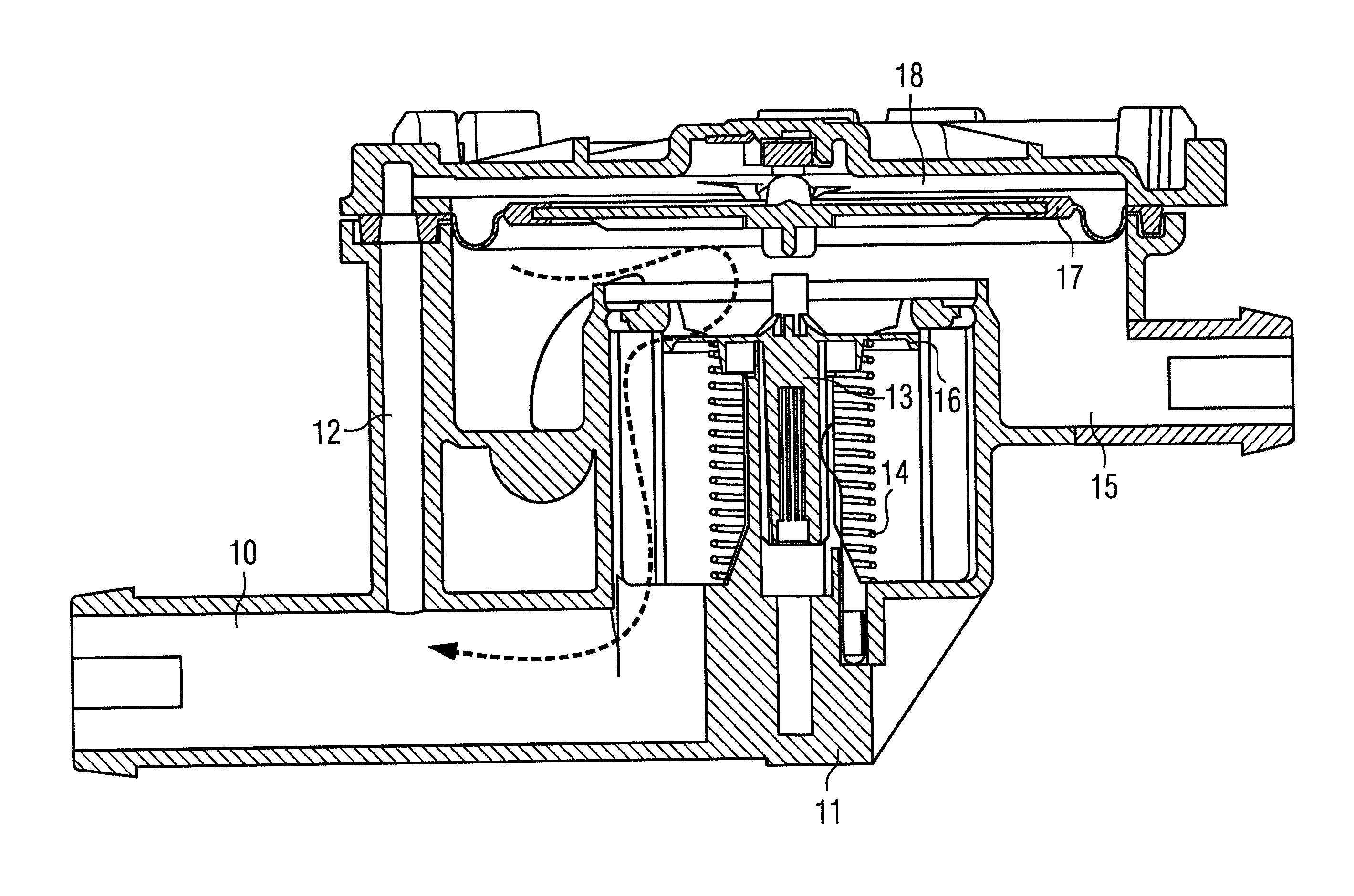
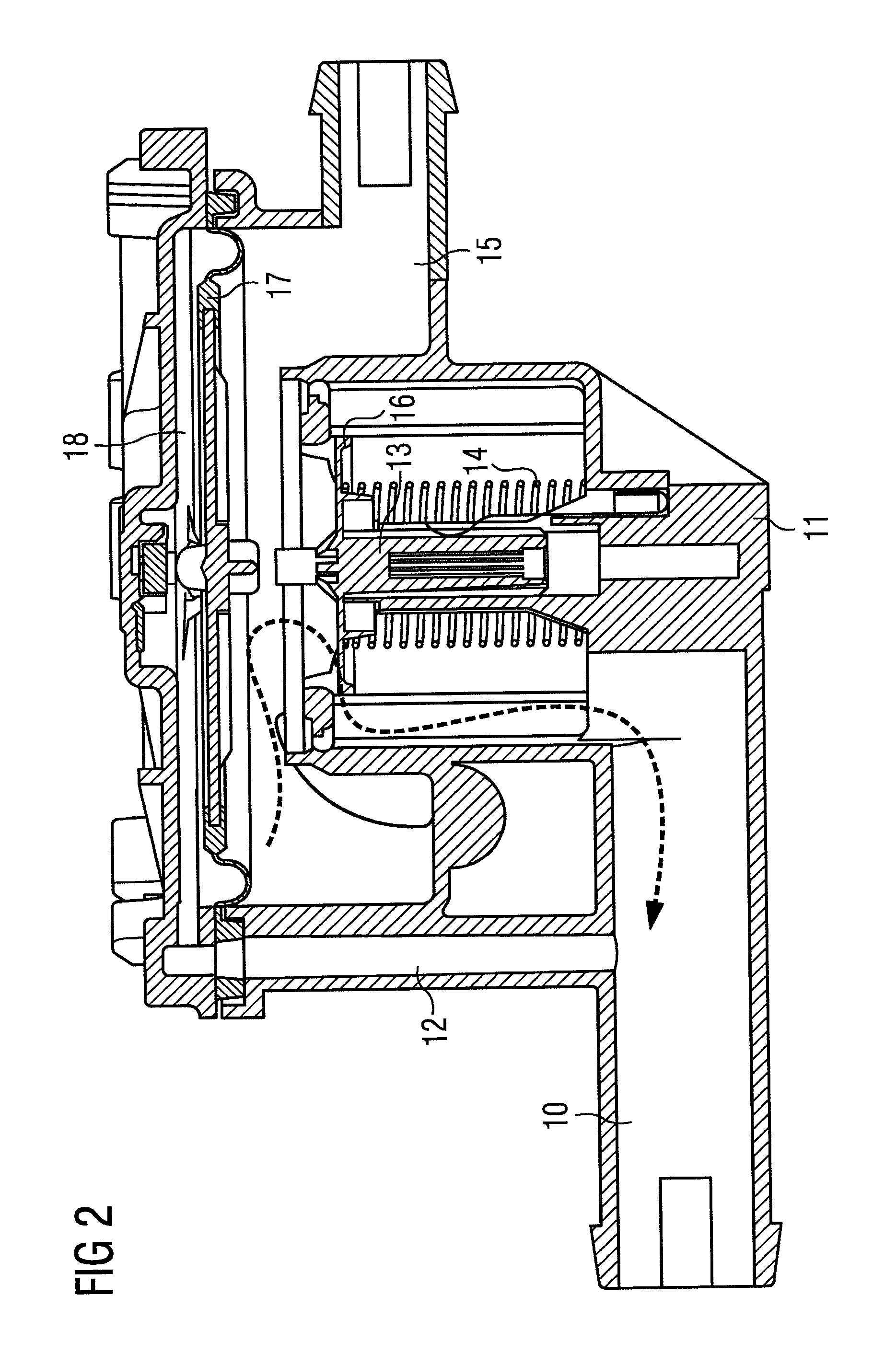
The present invention provides an internal combustion engine with a purge air pump that is capable of cleaning the fuel vapor store at a low cost. The purge air pump produces a large pressure difference to ensure effective cleaning without adding excessive costs. The pump is integrated into the valve unit, reducing additional expenses for housing, cabling, and installation. The use of an electric motor further promotes a low-cost and simple solution. Overall, the invention provides a valve unit and purge air pump constructional unit that minimizes additional outlay.

Problems solved by technology

However, the pressure to reduce fuel consumption has led to the introduction in motor vehicles of measures that decisively reduce the time in which a sufficient vacuum is available.
However, these methods are complex.

Method used


Image

  • Internal combustion engine with improved tank cleaning
  • Internal combustion engine with improved tank cleaning
  • Internal combustion engine with improved tank cleaning

Examples


Embodiment Construction

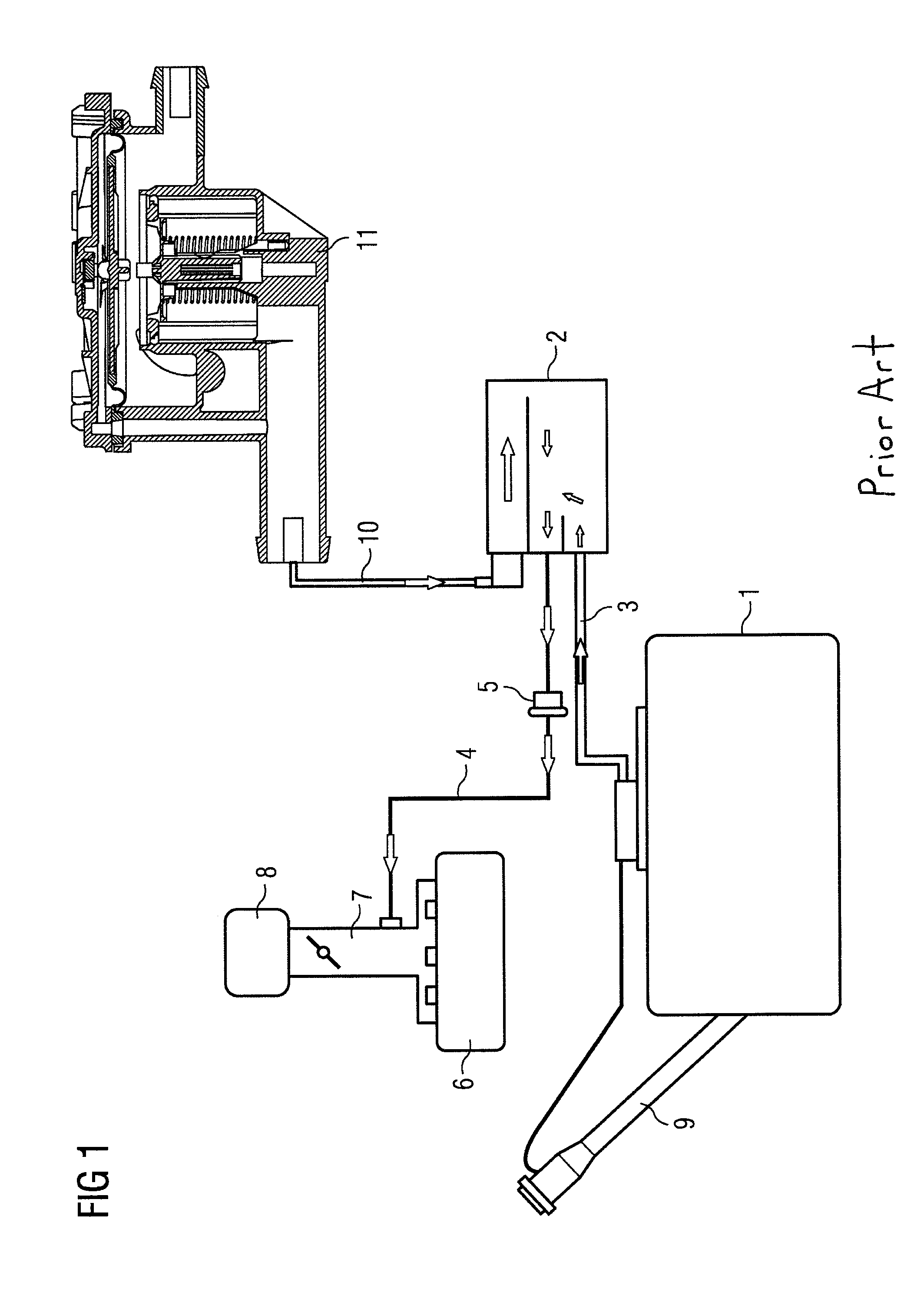
[0032]FIG. 1 shows schematically an internal combustion engine 6 having an intake air section 7 and an air filter 8. The internal combustion engine 6 is provided with a fuel tank 1 having a filler neck 9. A line 3 leads from the fuel tank 1 to a fuel vapor store 2, which can be a store filled with activated carbon, for example. Leading off from the fuel vapor store 2 to the air intake section 7 of the internal combustion engine 6 is a connecting line, in which a vent valve 5 is arranged. Also connected to the fuel vapor store 2 is an air admission line 10, which leads to a valve unit 11 that controls air admission to and venting of the fuel vapor store 2 and hence of the fuel tank 1.

[0033]The system illustrated in FIG. 1 belongs to the prior art. During operation, the fuel vapors collect in the fuel vapor store 2 and are absorbed by the activated carbon arranged in the store 2. When the store 2 is to be regenerated, the vent valve 5 is opened, establishing a connection between the f...


PUM


Abstract

An internal combustion engine having a fuel tank, a fuel vapor store for storing fuel vapors that escape from the fuel tank, having a connecting line between the fuel vapor store and an air intake tract to conduct fuel vapors from the fuel vapor store into the air intake tract during a regeneration phase, a valve arranged in the connecting line, an aeration line for the fuel vapor store, and having a valve arranged in the aeration line for controlling the aeration of the fuel vapor store. A purge air pump arranged in the aeration line is integrated into the valve unit for controlling the aeration of the fuel vapor store. Effective purging or regeneration of the fuel vapor store is attained even when no negative pressure or only a low negative pressure is provided by the air intake tract.

Description

CROSS REFERENCE TO RELATED APPLICATION[0001]This is a U.S. national stage of application No. PCT / EP2011 / 072464, filed on 12 Dec. 2011. Priority is claimed on German Application No.: 10 2010 054 668.2 filed 15 Dec. 2010, the content of which is incorporated here by reference.BACKGROUND OF THE INVENTION[0002]1. Field of the Invention[0003]The present invention relates to an internal combustion.[0004]2. Description of the Prior Art[0005]Modern motor vehicles now generally have a tank venting system. In this system, the fuel vapors formed in the fuel tank of the motor vehicle are adsorbed in a fuel vapor store, which is generally an activated carbon canister. The fuel vapor store is connected to the air intake section of the internal combustion engine by a connecting line (vent line). In the vent line there is a tank vent valve, by which the fuel vapor store can be either connected to the intake section or separated therefrom. From time to time, the fuel vapor store laden with fuel vapo...

Claims


Application Information

Patent Timeline
IPC IPC(8): F02M25/08
CPCF02M25/0818F02M25/0836F02M2025/0845F02M25/089F02M25/0872F02M25/08
Inventor GRASS, PHILIPPEWEIGL, MANFRED
Owner CONTINENTAL AUTOMOTIVE GMBH
Learn More