Battery system

Inactive Publication Date: 2013-10-03
MITSUBISHI HEAVY IND LTD
View PDF0 Cites 6 Cited by
  • Summary
  • Abstract
  • Description
  • Claims
  • Application Information

AI Technical Summary

Benefits of technology

[0013]According to the battery system of the present invention, the connection state of each of the

Problems solved by technology

However, when the physical connection is loosened, the power supply to the power load is interrupted.
This means that, in a ca

Method used


Image

  • Battery system
  • Battery system
  • Battery system

Examples


Example

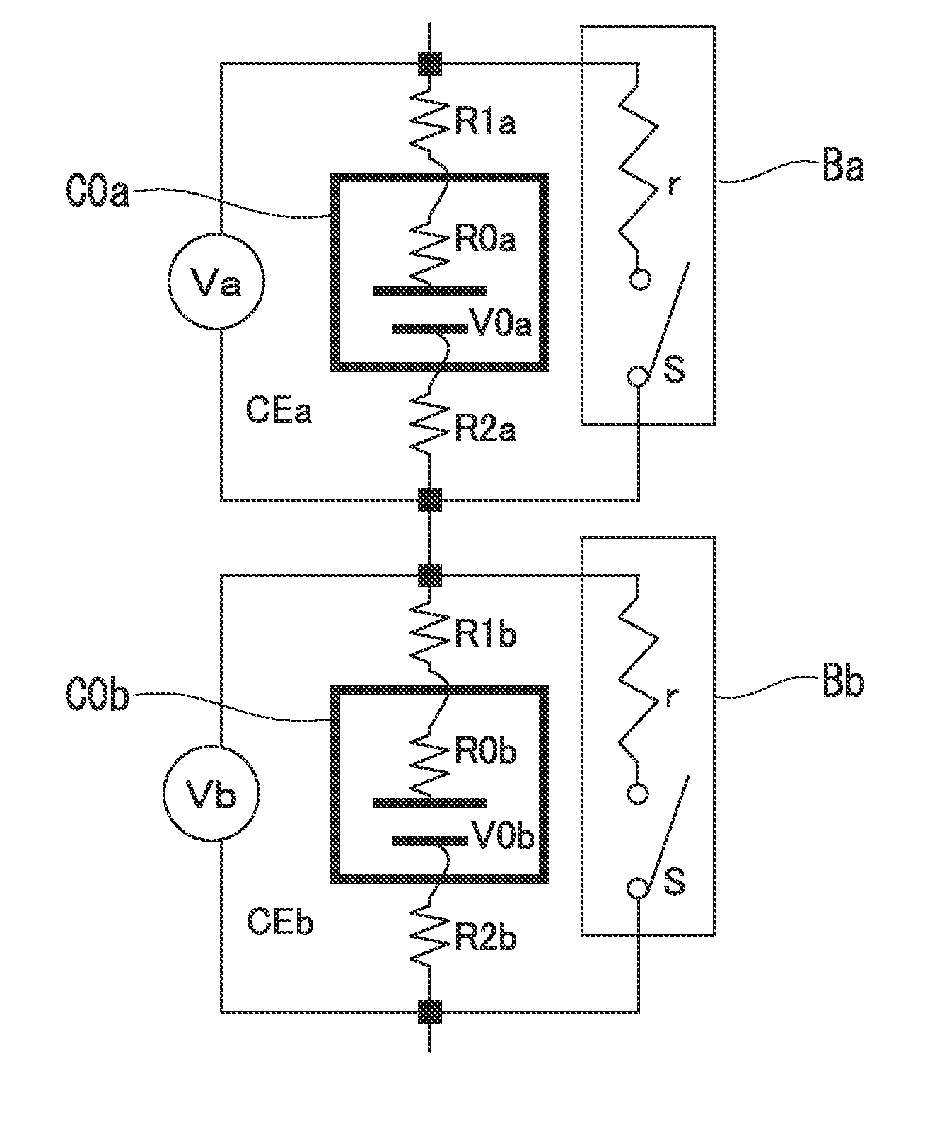
[0018]A battery system according to an embodiment of the present invention, as one of features, arranges a voltage sensor that measures a cell voltage to cause an electrical path on which the cell voltage of a battery cell is measured to include a contact resistance of a connection member as a power supply line and an electrode terminal, determines a state of electrical connection between the connection member and each battery cell at the time of starting up the battery system, and performs appropriate control and processing. Hereinafter, the battery system will be described in detail with reference to the drawings.

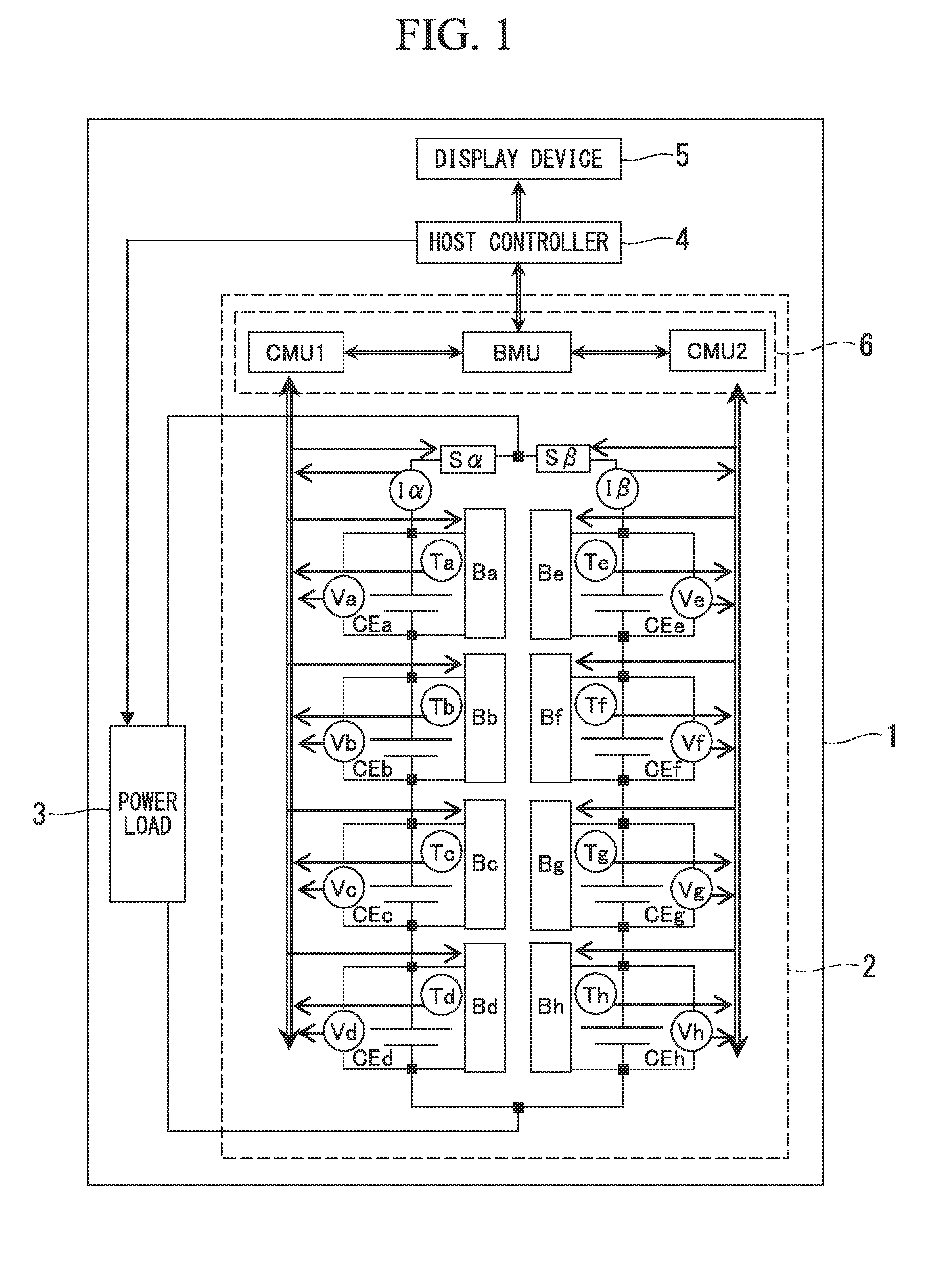
[0019]Hereinafter, the battery system according to the embodiment of the present invention will be described with reference to the drawings. FIG. 1 is a diagram illustrating the configuration of the battery system 1. The battery cell used in the battery system 1 can use any battery of a primary battery, a secondary battery, and the like depending on the use of the battery...


PUM


Abstract

A battery system includes: a first battery cell; a second battery cell; a power load supplied with current from the first battery cell and the second battery cell; a connection which electrically connects a negative electrode terminal of the first battery cell and a positive electrode terminal of the second battery cell; a connection which electrically connects the first negative electrode terminal and the second positive electrode terminal; a cell balancing circuit which causes electromotive voltages of the first battery cell and the second battery cell to be substantially equal; and a controller, wherein the controller enables the current to be supplied to the power load after causing the electromotive voltages of the first battery cell and the second battery cell to be substantially equal, thereby determining looseness of the connection.

Description

TECHNICAL FIELD[0001]The present invention relates to a battery system, and more particularly, to a battery system which determines a connection state between battery cells of a battery pack.[0002]Priority is claimed on Japanese Patent Application No. 2010-274382, filed Dec. 9, 2010, the content of which is incorporated herein by reference.BACKGROUND ART[0003]Battery cells used in a battery system are generally used in a form of a battery pack. That is, mostly, a plurality of battery cells are connected in series or in parallel using a connection as a power supply line to be used as a battery pack. The physical connection between the connection and an electrode terminal of the battery cell is made by using a screw or the like. The battery pack supplies power to, for example, a power load provided in the battery system.[0004]However, when the physical connection is loosened, the power supply to the power load is interrupted. In addition, in a case where the looseness further progress...

Claims


Application Information

Patent Timeline
IPC IPC(8): G01R27/02G01R31/36H02J7/00
CPCB60L3/0046Y02T10/7088B60L11/1866B60L11/1879B60L2200/10B60L2200/32B60L2200/36B60L2200/42B60L2230/22B60L2230/24B60L2240/545B60L2240/547B60L2250/10B60L2250/16B60L2250/28G01R31/04G01R31/362G01R31/3658H02J7/0016G01R27/02Y02T10/7005Y02T90/12Y02T10/7061Y02T10/7055B60L2240/549B60L2200/26B60L11/1803B60L50/51B60L50/64B60L53/51B60L53/52B60L58/10B60L58/22G01R31/3835G01R31/396G01R31/66Y02T10/70Y02T10/7072
Inventor TAKATSUJI, HIDEYASU
Owner MITSUBISHI HEAVY IND LTD
Why Eureka
Try Eureka