Mobile device and antenna array therein

a mobile device and antenna array technology, applied in the field of mobile devices, can solve the problems of reducing the communication quality of the mobile device, the antenna array for transmitting data usually occupies a lot of space, and the antenna array cannot dynamically receive and transmit signals at different directions

Active Publication Date: 2013-10-03
HTC CORP
View PDF3 Cites 37 Cited by
  • Summary
  • Abstract
  • Description
  • Claims
  • Application Information

AI Technical Summary

Problems solved by technology

Traditionally, an antenna array for transmitting data usually occupies a lot of space in a mobile device.
Furthermore, when the mobile device is moved or...

Method used


Image

  • Mobile device and antenna array therein
  • Mobile device and antenna array therein
  • Mobile device and antenna array therein

Examples


Embodiment Construction

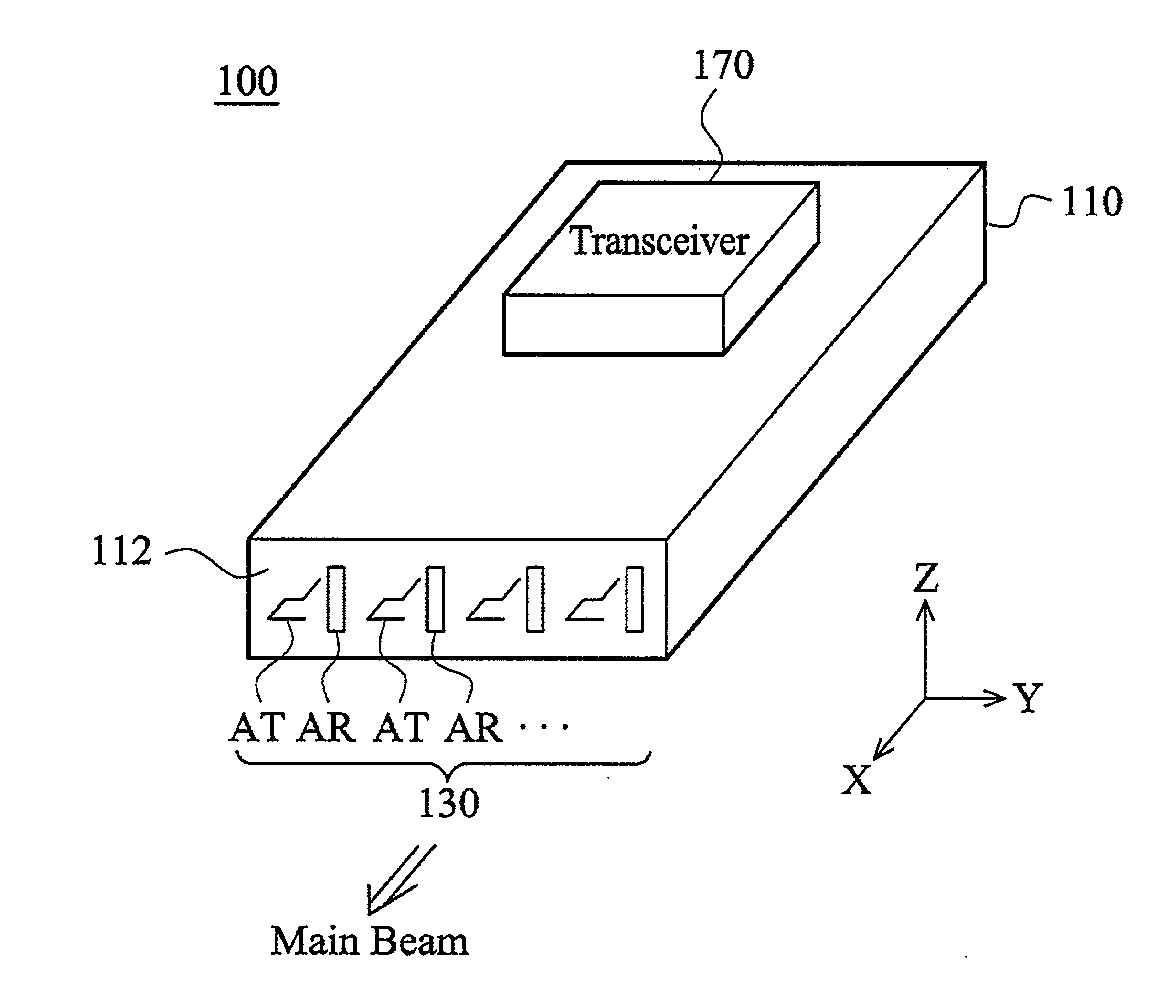
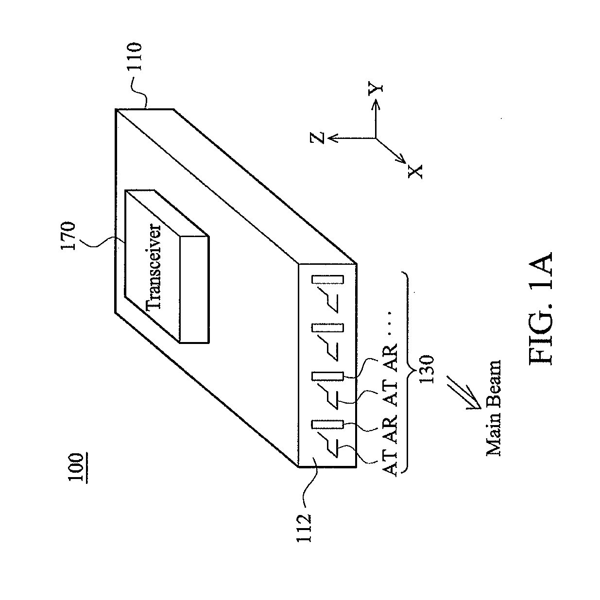
[0027]FIG. 1A is a pictorial drawing for illustrating a mobile device 100 according to an embodiment of the invention. The mobile device 100 may be a smart phone, a tablet, or a notebook. As shown in FIG. 1A, the mobile device 100 at least comprises a dielectric substrate 110, an antenna array 130, and a transceiver 170. A skilled person in the art can comprehend that the mobile device 100 may further comprise a processor, a display module, a touch module, an input module, and other electronic components even if they are not shown in FIG. 1A. In some embodiments, the dielectric substrate 110 is an FR4 substrate or an LTCC (Low Temperature Co-fired Ceramics) substrate, and the transceiver 170 is a TR (Transmission and Reception) chip, which may be disposed on two sides of the dielectric substrate 110. The transceiver 170 is electrically coupled to the antenna array 130, and is configured to transmit or receive a signal.

[0028]The antenna array 130 is close to a lateral edge 112 of the...


PUM


Abstract

A mobile device at least includes a dielectric substrate, an antenna array, and a transceiver. The antenna array at least includes a first antenna and a second antenna. The first and second antennas are both embedded in the dielectric substrate. The first and second antennas have different polarizations. The transceiver is coupled to the antenna array so as to transmit or receive a signal. The polarization of the antenna array may be dynamically adjusted by controlling a phase difference between the first antenna and the second antenna.

Description

CROSS REFERENCE TO RELATED APPLICATIONS[0001]This application is a Continuation-In-Part of application Ser. No. 13 / 435,867, filed on Mar. 30, 2012, the entirety of which is incorporated by reference herein.BACKGROUND OF THE INVENTION[0002]1. Field of the Invention[0003]The subject application generally relates to a mobile device, and more particularly, relates to a mobile device comprising an antenna array.[0004]2. Description of the Related Art[0005]With the progress of mobile communication technology, a camera or video recorder in a mobile device can retrieve high-resolution images and videos. Some high-end mobile devices use HDMI (High-Definition Multimedia Interface) cables as an interface to transmit high-resolution audio / video data to other display devices. However, it is more convenient for people to use wireless transmission, in particular, a 60 GHz band which has sufficient bandwidth, for transmitting high-quality video data.[0006]Traditionally, an antenna array for transmi...

Claims


Application Information

Patent Timeline
IPC IPC(8): H01Q21/00
CPCH01Q21/00H01Q21/06H01Q1/525H01Q21/065H01Q21/067H01Q21/28H01Q1/40H01Q13/18
Inventor LU, YU-CHUNLIN, YI-CHENGRAO, PEI-ZONGTUNG, WEI-SHIN
Owner HTC CORP
Why Eureka
Try Eureka