Unlock instant, AI-driven research and patent intelligence for your innovation.

Fluid motor under variable pressure

Inactive Publication Date: 2013-10-03
FIOROTTO TOMAS ALEJANDRO
View PDF1 Cites 0 Cited by
  • Summary
  • Abstract
  • Description
  • Claims
  • Application Information

AI Technical Summary

Benefits of technology

The invention is a device that uses the pressure of combustion to generate power. It consists of a submerged turbine that is connected to a cylinder block. The cylinder block has a unique valve that can release the gases of combustion and allow air to flow into the device for further combustion. The parts of the device are made in a practical way using metal casting. The technical effect of this invention is that it allows for the effective use of combustion pressure to generate power in a simple and cost-effective way.

Problems solved by technology

Both types are subject to a loss of energy due to the contact of their parts that also generate deterioration of a great part of the motor.

Method used


Image

  • Fluid motor under variable pressure
  • Fluid motor under variable pressure
  • Fluid motor under variable pressure

Examples


Embodiment Construction

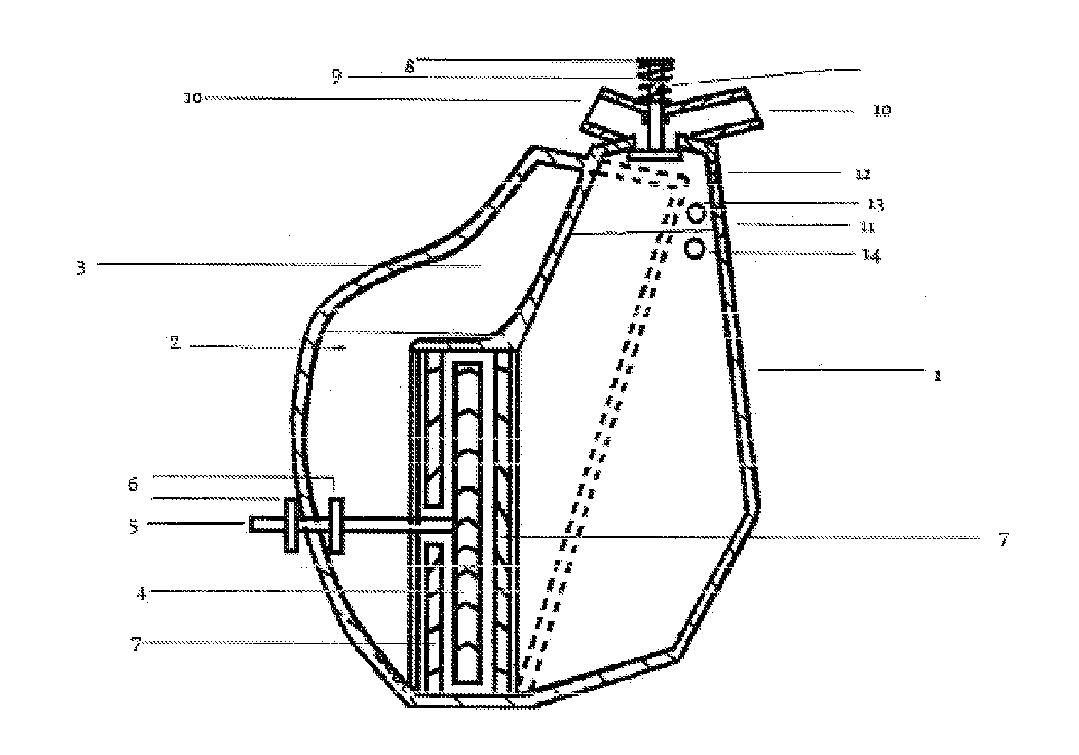
[0011]As can be observed from the drawings, the present invention is comprised of a conical cylinder 1, therein containing liquid 2 and gas flow. The conical cylinder is encompassed almost totally by a cavity 3 that contains also part of the pressurized liquid flow and gas flow.

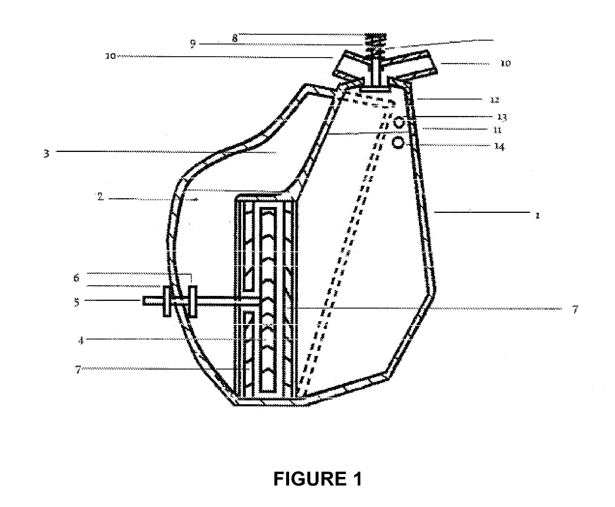
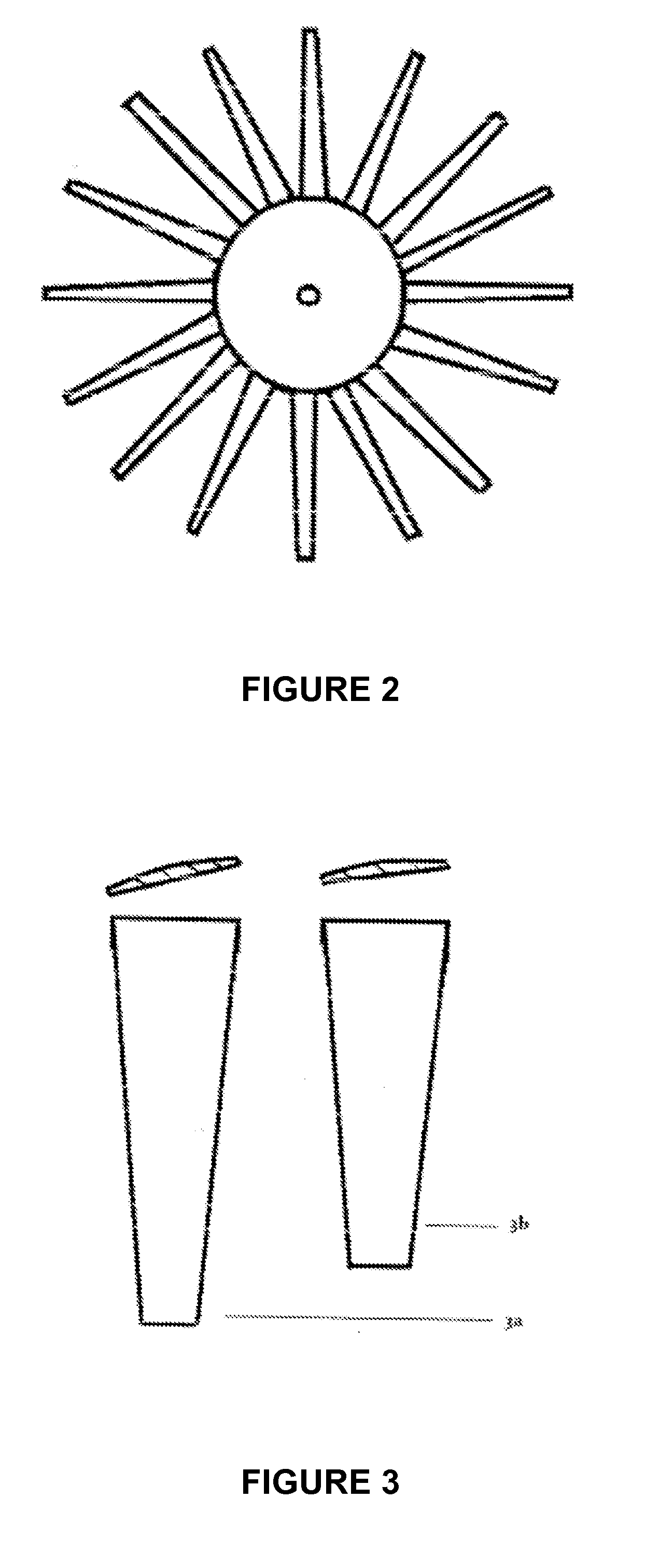
[0012]The conical cylinder 1 contains, also in its interior, a turbine 4 that contains in its shaft 5 two buffer stops that keep it in place; blades 7 deflect the liquid flow towards the turbine. At the upper part of the conical cylinder 1 there is a valve 8 supported by a spring 9, next to it there are gas input and output cavities 10 for placing the injector 11, the spark plug 12 and the ignition sensor 13 and injection 14.

OPERATION

[0013]There follows the description in numbered steps of the operation of such invention:

[0014]1. The injector injects combustible to the air compressed by the liquid flow activated by the compression cavity, then the mixture is initiated through the order of the two injection se...


PUM


Abstract

A fluid motor under variable pressure, wherein variation of pressure is generated by combustion of a combustible, after said process the liquid flow of the motor returns to its place activated by pressurization of a compressed gas that is within a cavity that encompasses the combustion chamber almost totally. This liquid flow energy in movement is collected by a turbine that is located within said motor.

Description

TITLE AND TECHNICAL FIELD OF THE INVENTION[0001]The present invention relates to means for generating kinetic energy of the type comprising internal combustion motors, through which the generation of kinetic energy is simplified to one shaft.STATE OF THE ART AND PROBLEM TO BE SOLVED[0002]To date, a great amount of methods of generation of kinetic energy through internal combustion motors are known, as is the case of the internal combustion motor of the Otto cycle and the motor of the Diesel cycle. Both types are subject to a loss of energy due to the contact of their parts that also generate deterioration of a great part of the motor. The invention, on the other hand, consists of few parts and a certain amount of liquid flow that achieves savings in raw material and reduces wear thereof.[0003]This is achieved, in the invention, when changing the pistons, connecting rods and crankshaft used in the Otto and Diesel cycle motors for a submerged turbine in a fluid subjected to the action...

Claims


Application Information

Patent Timeline
IPC IPC(8): F04B17/05
CPCY02E10/28F03G7/00Y02E10/20
Inventor FIOROTTO, TOMAS ALEJANDRO
Owner FIOROTTO TOMAS ALEJANDRO
Features
  • R&D
  • Intellectual Property
  • Life Sciences
  • Materials
  • Tech Scout
  • Unparalleled Data Quality
  • Higher Quality Content
  • 60% Fewer Hallucinations
Learn More