Electrical submersible pump assembly for separating gas and oil

a technology of electric submersible pumps and assembly parts, which is applied in the direction of piston pumps, positive displacement liquid engines, and well accessories, etc., can solve the problems of high gas-to-oil ratio, ineffective just-described measures, and production losses across the field, so as to improve pump efficiency

Active Publication Date: 2013-10-03
SAUDI ARABIAN OIL CO
View PDF4 Cites 27 Cited by
  • Summary
  • Abstract
  • Description
  • Claims
  • Application Information

AI Technical Summary

Benefits of technology

[0012]In the present invention, separation of gas and liquid is done downhole as part of an electrical submersible pump. This will eliminate the need for the large rotating equipment and upgrades needed to perform surface multi-phase pumping. It also will...

Problems solved by technology

While submersible pumps of the type described in the '261 patent are widely used in the oil industry, such pumps may not be suitable for use in wells having a high gas-to-oil ratio, i.e., wells having a gas/oil ratio exceeding approximately 60% free ...

Method used


Image

  • Electrical submersible pump assembly for separating gas and oil
  • Electrical submersible pump assembly for separating gas and oil
  • Electrical submersible pump assembly for separating gas and oil

Examples


Embodiment Construction

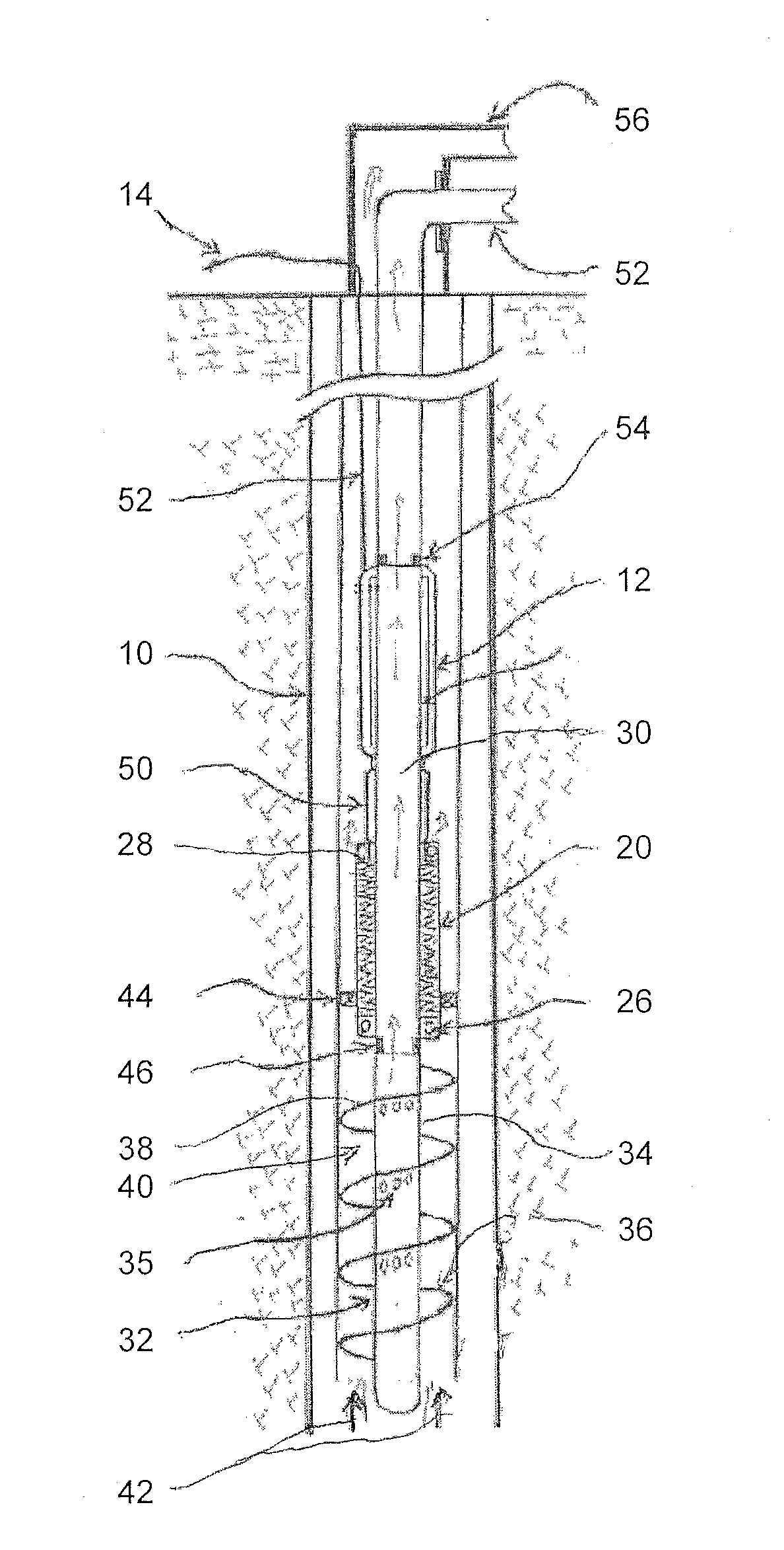
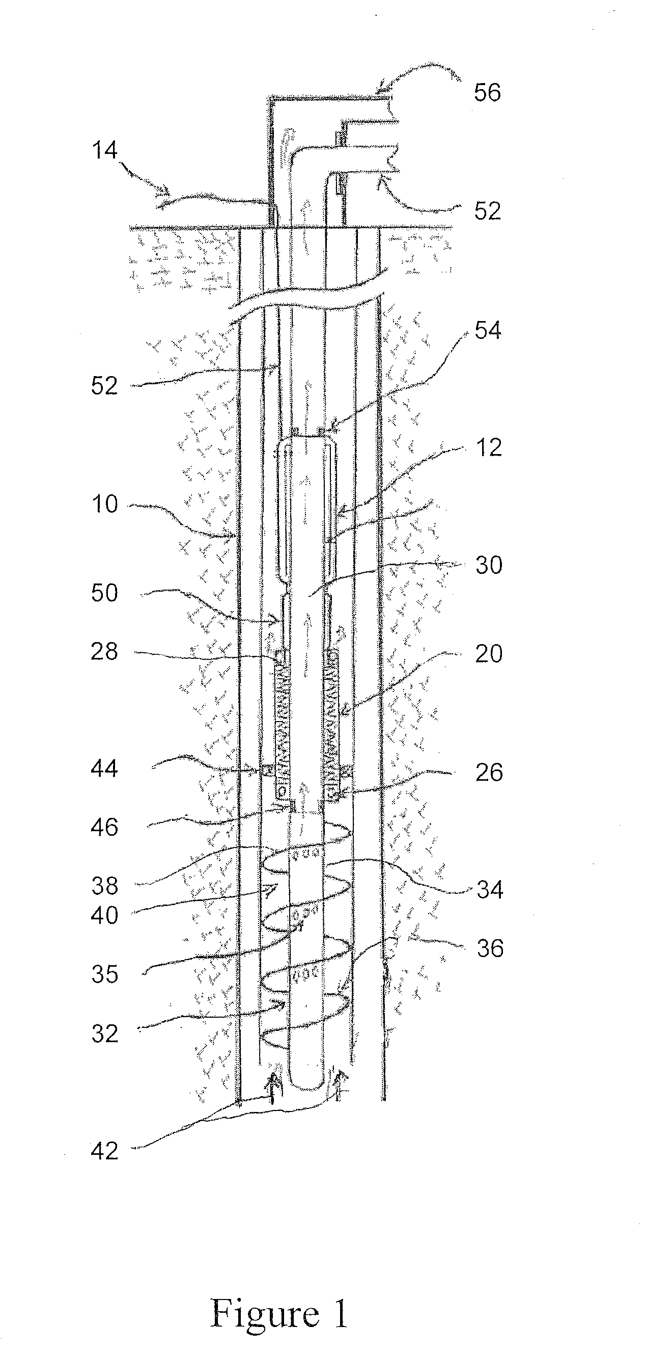
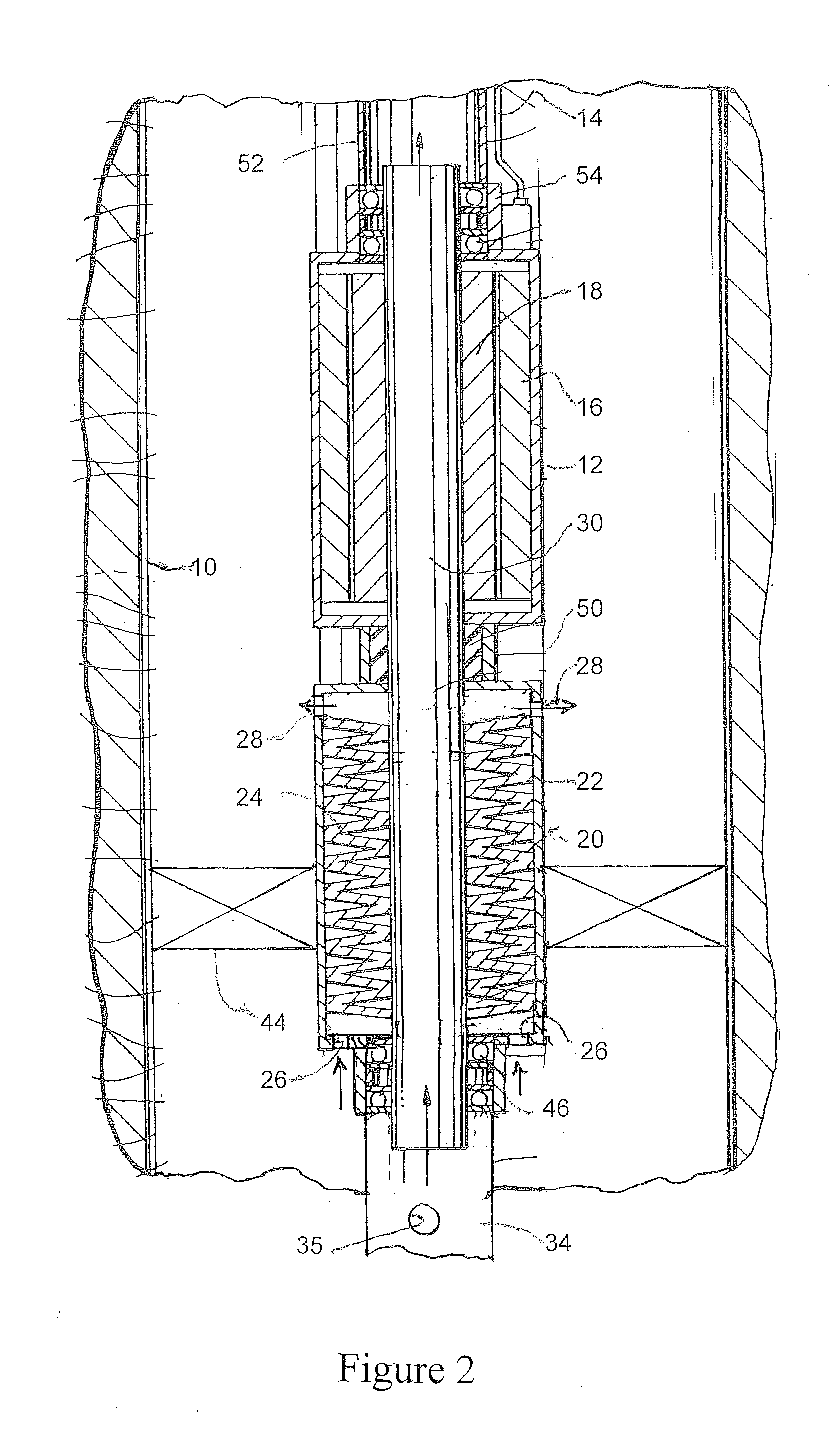
[0016]FIG. 1 depicts schematically a well having a well casing 10 containing a gas / oil mixture with a high gas-to-oil ratio. An electrical submersible pump assembly, portions of which are shown in more detail in FIG. 2, comprises an electrical motor 12 which receives power through an electrical cable 14. The electrical motor includes a stator 16 and a rotor 18.

[0017]A pump 20, which may be of the type described in U.S. Pat. No. 6,120,261, which is incorporated by reference herein, includes a pump housing 22 and internal pump stages 24. The pump housing 22 has intake openings 26 at its lower end, and outlet openings 28 at its upper end. The intake openings 26 may be located on an end wall of the pump housing 22, or on the sidewall portions of the pump housing 22, as desired. The pump discharge points (outlet openings 28) are located at the end of the pump stages 24 (and may be located in the sidewall or upper end of the pump housing).

[0018]A hollow, tubular drive shaft 30 has an uppe...


PUM


Abstract

An electrical submersible pump assembly for use in a well, including a well having a high gas-to-liquid ratio has a motor, a hollow, tubular drive shaft which drives the pump, and a liquid-gas separator assembly upstream of the pump intake. The liquid-gas separator has a hollow tubular portion, which communicates with the open, lower end of the drive shaft, openings through its sidewall, and a closed lower end. The sidewall also includes at least one outwardly extending projection shaped for urging liquid contained in a liquid/gas mixture flowing towards the pump outwardly, away from the sidewall openings. Preferably, the outwardly extending projection comprises a helical blade which, using either the well casing or a separate sheath, defines a helical channel through which the oil-gas mixture flows prior to reaching the pump intake. The centrifugal force in the channel forces the oil component away from the openings and forces the gas component through the openings, where such gas may be vented to the surface.

Description

BACKGROUND OF THE INVENTION[0001]The present invention relates to electrical submersible pumps for use in pumping oil from the borehole of a well to the surface.[0002]An example of a known electrical submersible pump assembly is disclosed in commonly owned U.S. Pat. No. 6,120,261. The assembly includes an electric motor section and a pump section. A hollow drive shaft has one end fixed to the rotor of the motor. The other end of the drive shaft extends into the pump portion of the assembly, to rotate pump impellers contained in a pump housing. Oil from the reservoir enters the hollow drive shaft, and is drawn into the lower end of the pump housing through a series of holes formed in the shaft. The impellers pump the oil upwardly to the upper end of the pump housing, where the oil is forced through another series of holes back into the hollow shaft. The upper end of the drive shaft is connected to piping for thereafter delivering the oil to the surface.[0003]While submersible pumps o...

Claims


Application Information

Patent Timeline
IPC IPC(8): F04B17/03
CPCF04B17/03E21B43/128E21B43/38F04B47/06
Inventor NOUI-MEHIDI, MOHAMED NABILAHYAD, RABEA
Owner SAUDI ARABIAN OIL CO
Why Eureka
Try Eureka