Composting device

a composting device and composting technology, applied in the field of composting devices, can solve the problems of requiring months to produce usable compost, unable to facilitate the curing process and the composting process, and limited current residential composting assemblies, etc., to achieve the effect of facilitating and exposing the refuse surfa

Inactive Publication Date: 2013-10-03
WHIRLPOOL CORP
View PDF10 Cites 16 Cited by
  • Summary
  • Abstract
  • Description
  • Claims
  • Application Information

AI Technical Summary

Problems solved by technology

However, current residential compost assemblies are limited in that they do not facilitate the curing process and the composting process in general.
The decomposition process may be accelerated by adding chemicals or bacteria to the ground refuse, however such an addition may still require months to produce usable compost.
Unfortunately, refuse may still be collected as the ground refuse is piling up.
This may present a problem in residences where users have limited outdoor space to store the refuse.
For instance, residents residing in urban areas may not have a backyard in which the refuse may be stored during the composting process.
Further, current composting devices do not have features which facilitate the cleansing of the device itself.
Thus without user action ground refuse may stick to the crevices and parts within the device causing an unpleasant odor to emanate from the device.
Further current residential composting devices are typically manually operated and are not configured to adjust the operating cycle based upon the content of the refuse.

Method used


Image

  • Composting device
  • Composting device
  • Composting device

Examples


Embodiment Construction

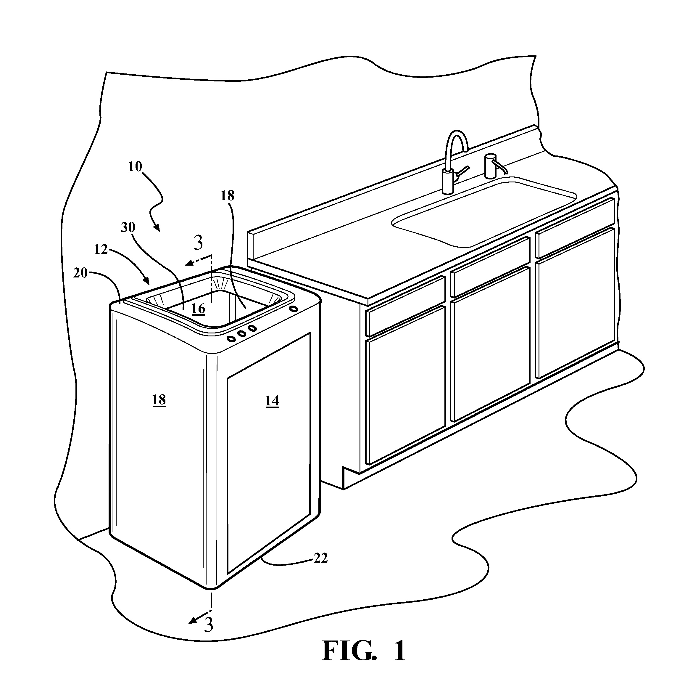
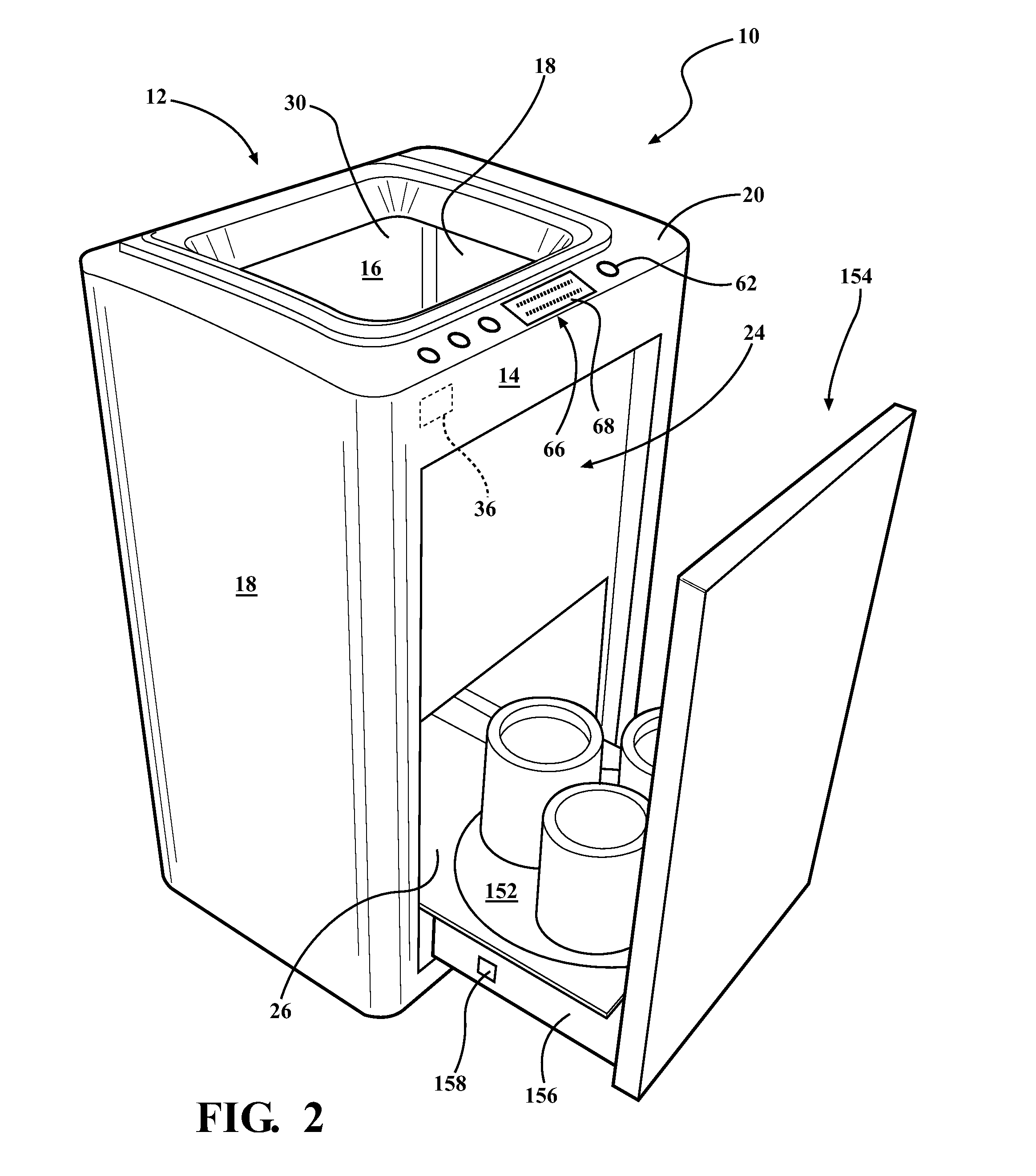
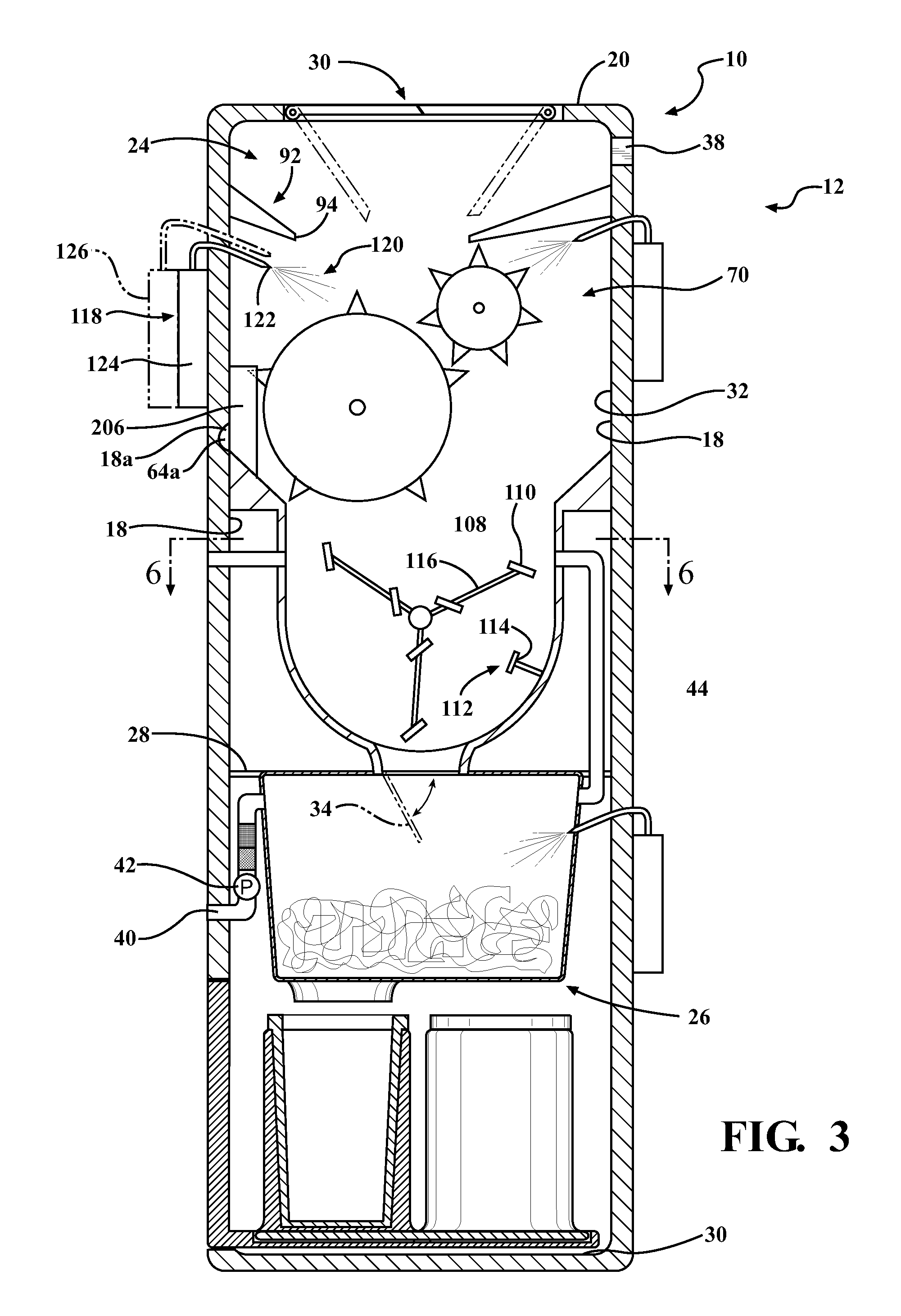
[0026]With reference first to FIGS. 1-3, a device 10 for transforming refuse into compost is provided. The device 10 includes a housing 12 having a front wall 14 spaced apart a back wall 16, and a pair of side walls 18 extending between the front and back walls 14, 16. The housing 12 also includes a top wall 20 opposite a bottom wall 22. The housing 12 may be formed of a rigid and durable material such as steel, a metal alloy, or a hardened polymer composite material.

[0027]A first chamber 24 and a second chamber 26 are disposed within the housing 12. The first chamber 24 may include a bottom floor 28 spaced apart the top wall 20 and the bottom wall 22. The bottom floor 28 extends between the side, front and back walls 18, 14, 16 so as to enclose the first chamber 24.

[0028]The top portion of the first chamber 24 is enclosed by the top wall 20 of the device 10 and may include a first opening 30 for receiving refuse. The inner surfaces of the side walls 18, and front and back walls 14,...


PUM

PropertyMeasurementUnit
thermal energyaaaaaaaaaa
temperatureaaaaaaaaaa
durableaaaaaaaaaa

Abstract

The invention relates to a device for transforming refuse into compost. The device includes a first chamber having a grinding mechanism to grind refuse. The device also includes a second chamber attached to the first chamber, and a conduit interconnecting the first chamber to the second chamber. The second chamber stores the ground refuse to promote the composting process, and the conduit allows thermal energy and moisture to be shared between the first and second chambers.

Description

CROSS-REFERENCE TO RELATED APPLICATIONS[0001]This application claims the benefit of U.S. Patent Application No. 61 / 619,569, filed Apr. 3, 2012 and U.S. Patent Application No. 61 / 641,942, filed May 3, 2012.FIELD OF THE INVENTION[0002]The invention relates to a compost device. More particularly, the invention relates to a compost device having a first chamber configured to grind refuse into particles and a second chamber configured to hold the ground refuse to facilitate curing operations.BACKGROUND OF THE INVENTION[0003]Compost devices are currently known and used. Residential compost devices are relatively small and configured to fit within the living spaces of a domestic user such as the kitchen or garage. However, current residential compost assemblies are limited in that they do not facilitate the curing process and the composting process in general.[0004]As is known by those skilled in the art, compost is formed when refuse comprising organic matter has been decomposed to a stat...

Claims


Application Information

Patent Timeline
Patent Type & Authority Applications(United States)
IPC IPC(8): C05F17/02
CPCC05F17/0247C05F17/0258C05F17/0282C05F17/0205C05F17/907C05F17/95C05F17/964C05F17/993Y02W30/40Y02P20/145B02C18/0084B02C23/02
Inventor BERBERET, SUZANNE M.BLANCHARD, WALTER T.BURGESS, BRENT M.DELGADO, KRISTOPHER L.DIBKEY, BRETTHABEGGER, DONALD J.KASPROWICZ, ANDREWMANN, EARL W.MURCH, WILLIAM L.PARK, JACK F.SONNENBERG, WESLEY A.
Owner WHIRLPOOL CORP
Why Eureka
Try Eureka