Building panel with a mechanical locking system

a locking system and building panel technology, applied in the field of building panels, can solve the problems of having to produce separate tongues, and achieve the effect of more stable and stronger locking system

Active Publication Date: 2013-10-10
VÄLINGE INNOVATION AB
View PDF0 Cites 128 Cited by
  • Summary
  • Abstract
  • Description
  • Claims
  • Application Information

AI Technical Summary

Benefits of technology

[0009]A further object is to provide a locking system with a flexible and displaceable tongue that may be formed out of the edge of the building panel. Such a system may simplify the production since no loose and additional part is necessary to produce and position at the correct position in the locking system.
[0038]The thickness of the outer wall of the displacement groove at a first and upper part of the displacement groove, above the upper surface of the tongue, is configured such that the resilient and displaceable tongue part is obtained. Also the thickness of the outer wall of the displacement groove at a second part of the displacement groove, below the resilient and displaceable part of the tongue, is configured such that the resilient and displaceable tongue part is obtained. The outer wall at the first and upper part and at the second part is not, according to certain embodiments of the second aspect, intended to break. The purpose of the displacement groove and the outer wall at the first and upper part and at the second part is to make the resilient and displaceable tongue part more resilient and to provide an improved locking strength.

Problems solved by technology

A drawback with the known system is that a separate tongue must be produced and special inserting machines are required to position the tongue in the displacement groove with high precision.

Method used


Image

  • Building panel with a mechanical locking system
  • Building panel with a mechanical locking system
  • Building panel with a mechanical locking system

Examples


first embodiment

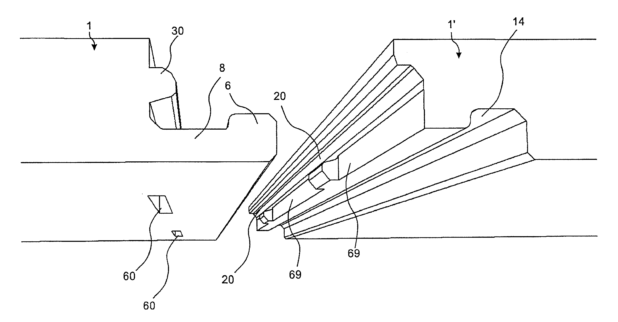
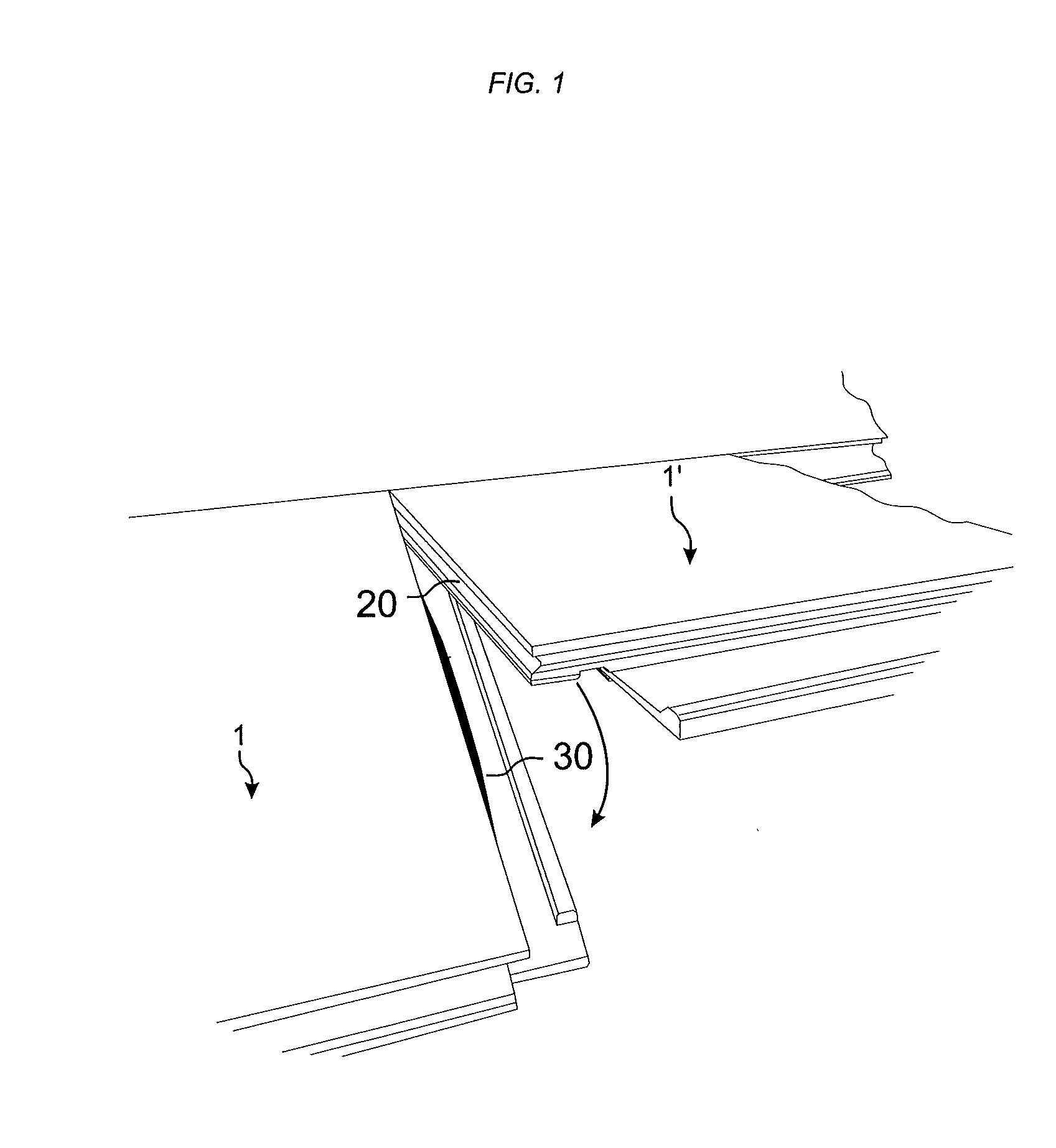
[0075]FIGS. 4, 5, 6a-c, 7a-d and 8b show a first embodiment comprising a tongue 30 with two displaceable parts 66 and three fixed parts 68, two displacement grooves 60, and a lower lip 31 of a tongue groove 20 with three recesses 69. The cross section in FIG. 6a is at the D-D line indicated in FIG. 8a and the cross section in FIG. 6b is at the C-C line indicated in FIG. 8a.

second embodiment

[0076]FIG. 8a shows a second embodiment comprising a tongue 30 with one displaceable part 66 and two fixed parts 68, one displacement groove 60, and a lower lip of the tongue groove 20 with two recesses 69.

[0077]The first embodiment is shown in a 3D view in FIGS. 4 and 5.

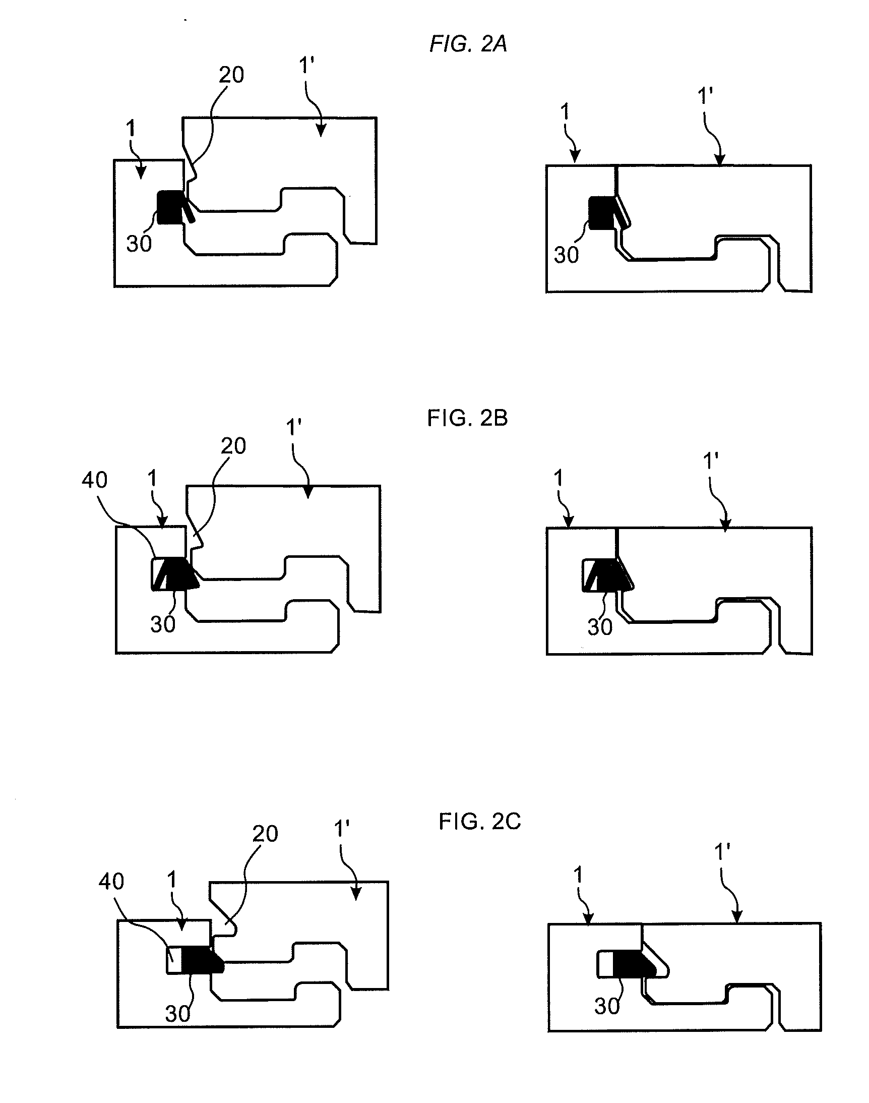
[0078]The cross sections in FIGS. 6a and b and the side view in FIG. 6c, show that a lower surface of the displaceable part 66 cooperates, for vertical locking of adjacent edges of the panels 1,1′, with a contact surface 70 of the lower lip 31 of the tongue groove 20. A vertical movement of the displaceable part is restrained, since the displaceable part of the tongue is continuous with the fixed part 68 of the tongue 30a.

[0079]The displacement groove 60 is formed from the underside of the first panel 1′ and comprises an inner wall 61, an outer wall 62, and an upper wall 67. The displacement groove 60 may be positioned, in relation to the edge of the first panel, such that the thickness of the outer wall at a first...


PUM

PropertyMeasurementUnit
vertical displacementaaaaaaaaaa
thicknessaaaaaaaaaa
resilientaaaaaaaaaa

Abstract

Building panels 1, 1′ provided with a mechanical locking system including a tongue 30, at an edge of a first panel 1, cooperating with a tongue groove 20, at an edge of an adjacent second panel 1′, for vertical locking of the building panels. The edge of the first panel is provided with a displacement groove 60, which is downwardly open, and includes an inner wall 61, an outer wall 62, and an upper wall 67. The tongue 30 is formed out of the edge of the first panel. A resilient and displaceable and part 66 of the tongue 30 is displaceable into the displacement groove 60.

Description

CROSS REFERENCE TO RELATED APPLICATIONS[0001]The present application claims the benefit of U.S. Provisional Application No. 61 / 620,233, filed on Apr. 4, 2012. The entire contents of U.S. Provisional Application No. 61 / 620,233 are hereby incorporated herein by reference in their entirety.FIELD OF THE INVENTION[0002]The present disclosure relates to a building panel such as a floor panel, a wall panel, a ceiling panel, a furniture component or the like, which is provided with a mechanical locking system, and a method for producing said building panel with said locking system.TECHNICAL BACKGROUND[0003]Building panels provided with a mechanical locking system comprising a displaceable and resilient tongue cooperating with a tongue groove for vertical locking is known and disclosed in, e.g., WO2006 / 043893. The tongue is a separate part and is made of e.g. plastic and inserted in a displacement groove at an edge of a panel. The tongue is pushed into the displacement groove during a vertic...

Claims


Application Information

Patent Timeline
Patent Type & Authority Applications(United States)
IPC IPC(8): E04F15/02
CPCE04F15/02038E04F15/10E04C2/38E04F2201/041E04F2201/042E04F2201/0146E04F13/076E04F2201/023E04F2201/043E04B1/541E04F13/0894E04F2201/0138E04F2201/044E04F13/0889
Inventor BOO, CHRISTIAN
Owner VÄLINGE INNOVATION AB
Why Eureka
Try Eureka