

Flange Joint and Method for Preventing a Fluid from Leaking Out Through a Flange Joint
a technology of flange joints and fluids, applied in the direction of liquid gas reaction processes, hose connections, thin film types, etc., can solve the problems of undesirable leakage, toxic materials or materials that can become explosive in certain mixtures, and cannot be allowed to leak through flange joints, so as to avoid excessive purging of safe sealing fluid into the process.
- Summary
- Abstract
- Description
- Claims
- Application Information
AI Technical Summary
Benefits of technology
Problems solved by technology
Method used
Image

Examples
Embodiment Construction
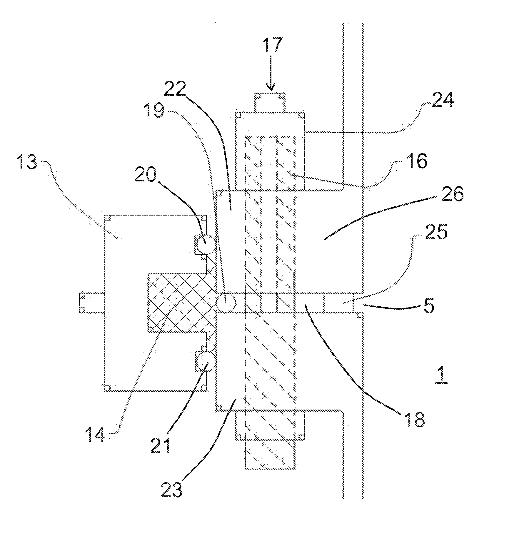
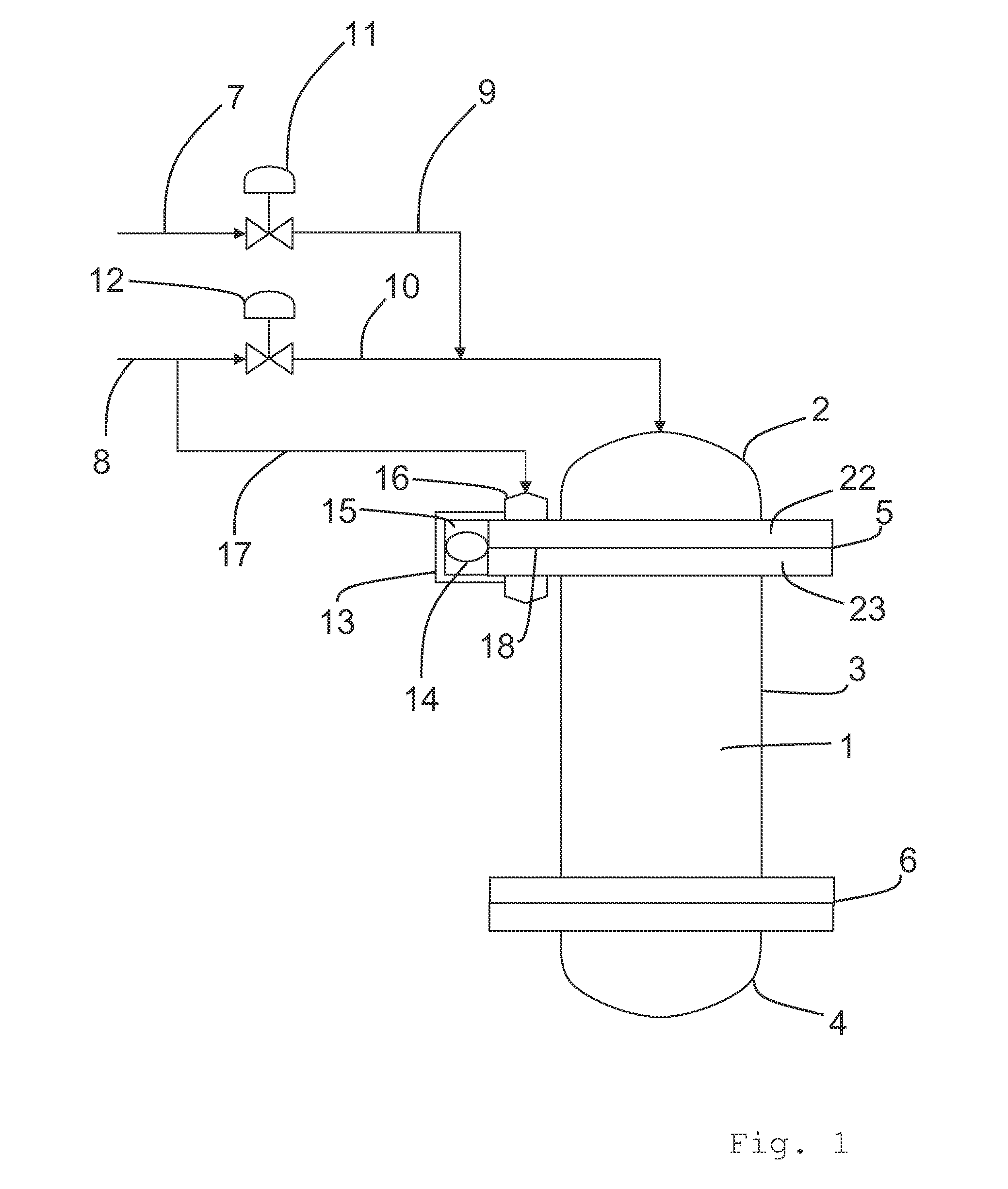
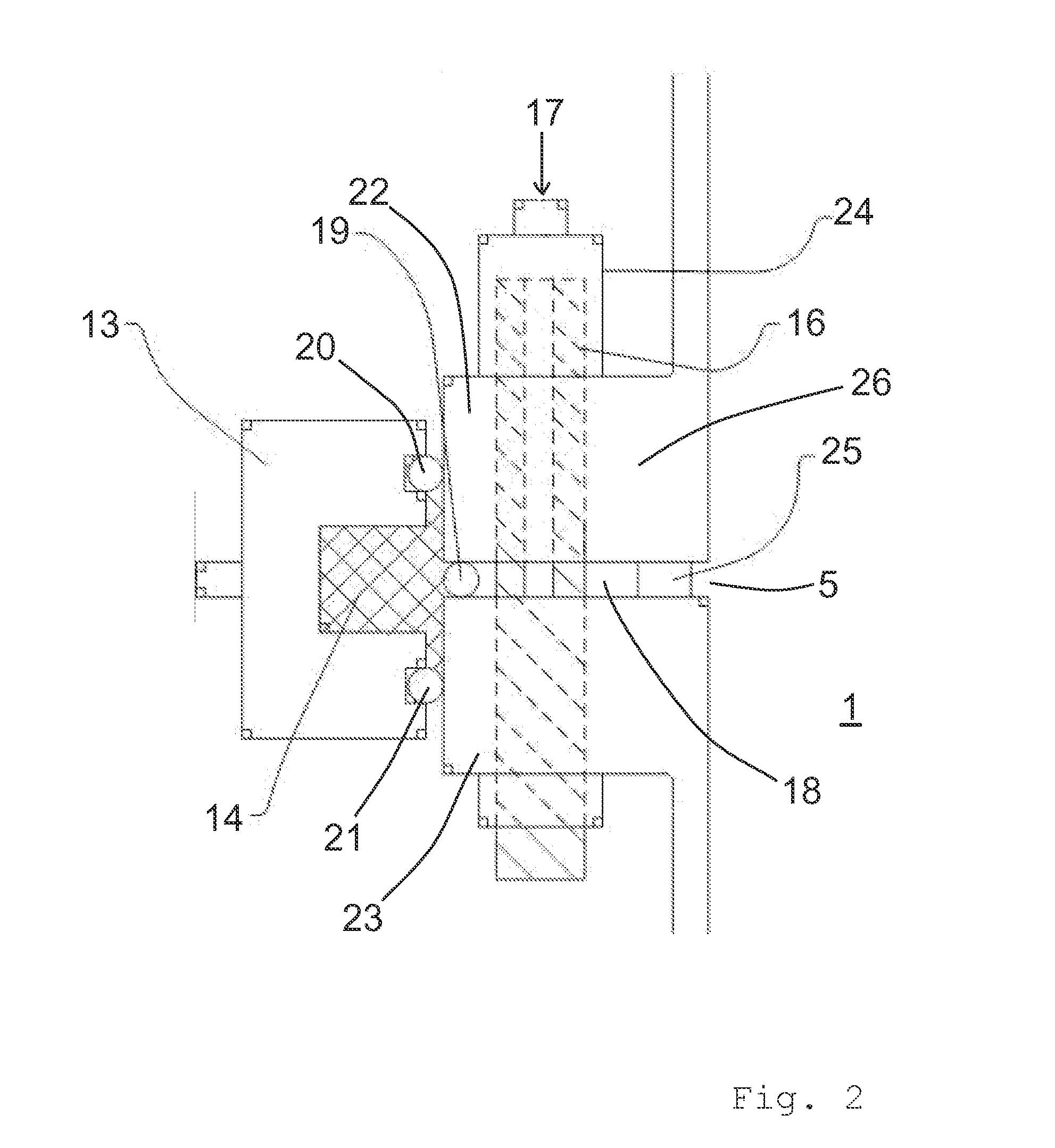
[0042]In FIG. 1 a reactor vessel 1 is formed of sections 2, 3 and 4. The sections are joined by flange joints 5&6. A hazardous chemical 7 and a non-hazardous chemical 8 are fed to the top of the reactor via lines 9&10 and control valves 11&12. Because chemical 7 is hazardous, it is important that it does not leak to the environment. Flange joint 5 has developed a leak and been sealed by a method according to the present invention. In FIGS. 1 & 2, a clamp 13 has been fitted to the flange joint 5 and a peened wire 19 inserted into the flange joint 5 to form a partial barrier. The clamp forms seals 20&21 with the outer end of the flanges 22&23 that form the flange joint 5. A sealant 14 has been applied in the cavity 15 between the clamp 13, peened wire 19 and the outer ends of the flanges 22&23 that form the flange joint 5. The sealant 14 is prevented from ingressing through the flange joint 5 by the peened wire 19 and has sealed the outside of the flange joint 5. A slotted stud 16 has...
PUM
 Abstract
Description
Claims
Application Information