Communication system and communication method
a communication system and communication method technology, applied in the field of communication system and communication method, can solve problems such as communication delay, and achieve the effect of reducing the number of processing rules stored, reducing the number of requests for route determination and processing rules
- Summary
- Abstract
- Description
- Claims
- Application Information
AI Technical Summary
Benefits of technology
Problems solved by technology
Method used
Image
Examples
first exemplary embodiment
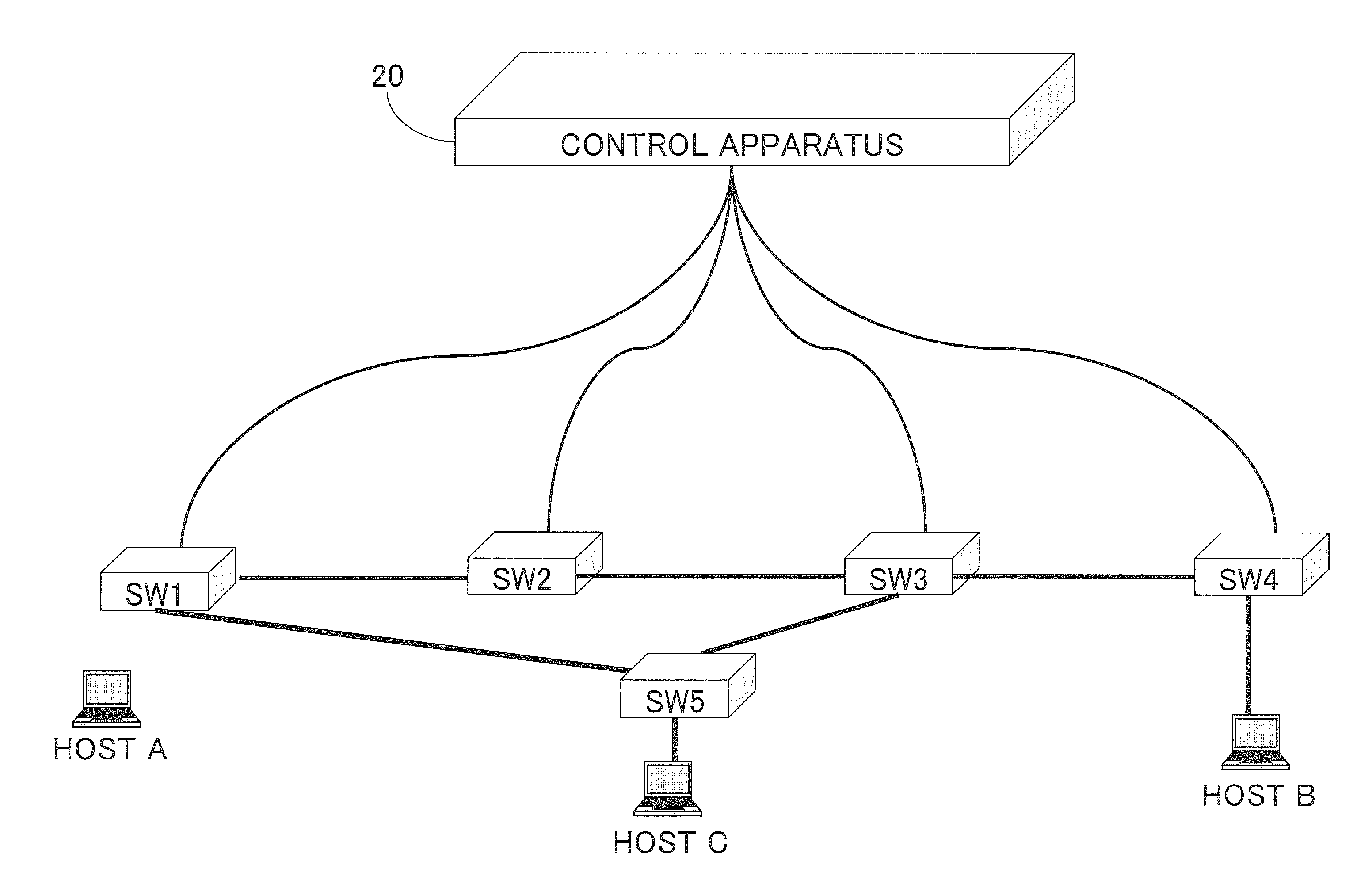
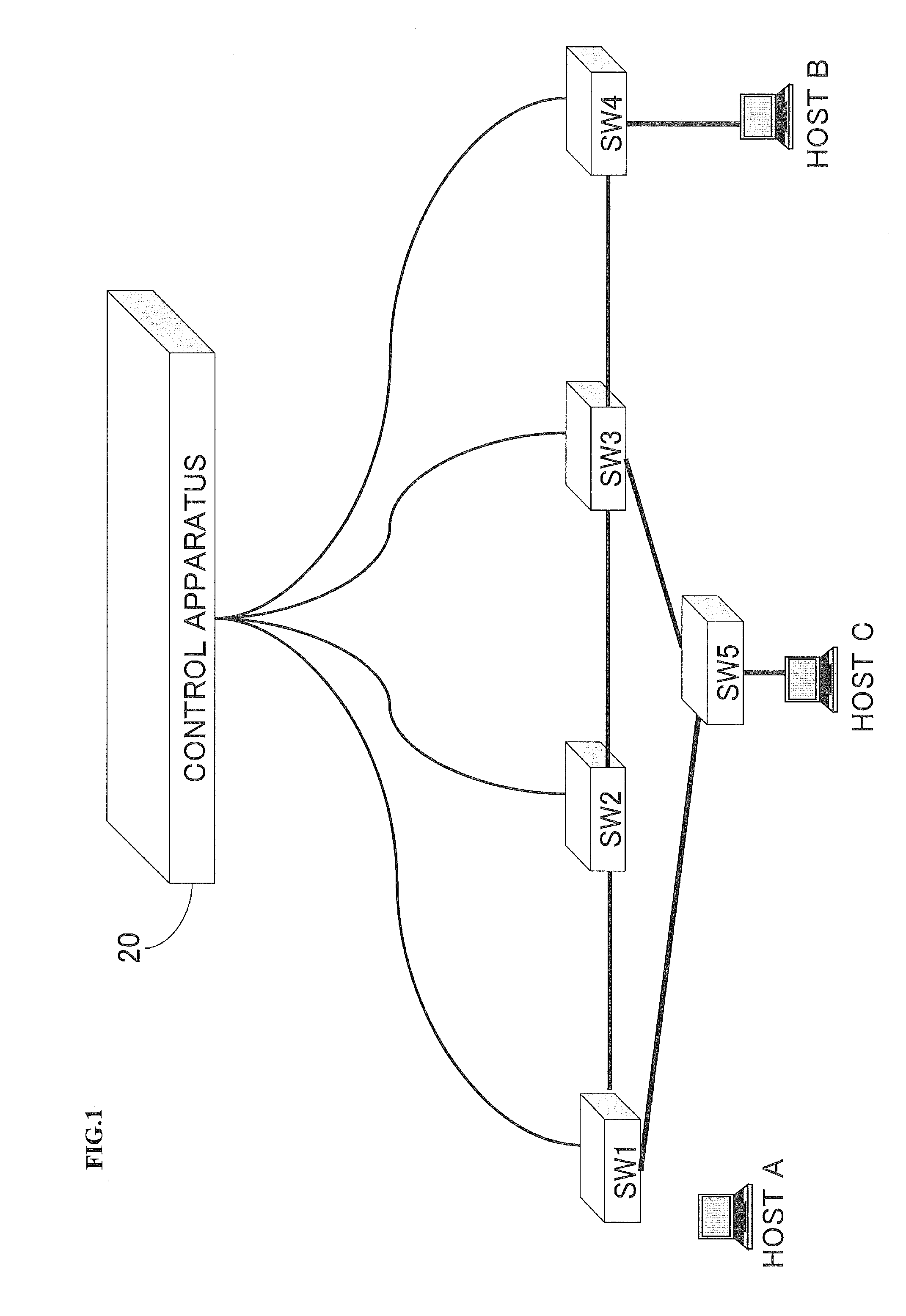
[0057]A communication system according to a first exemplary embodiment will be described with reference to the drawings. FIG. 1 is a diagram showing an example of a configuration of a communication system according to the present exemplary embodiment.
[0058]With reference to FIG. 1, five switches SW1-SW5, a control apparatus (controller) 20, and hosts A-C that communicate via switches SW1-SW5 are shown. FIG. 1 shows five switches SW1-SW5, the control apparatus (controller) 20, and three hosts A-C as an example. However, the number of these apparatus included in the communication system is not limited to the mode shown in FIG. 1.
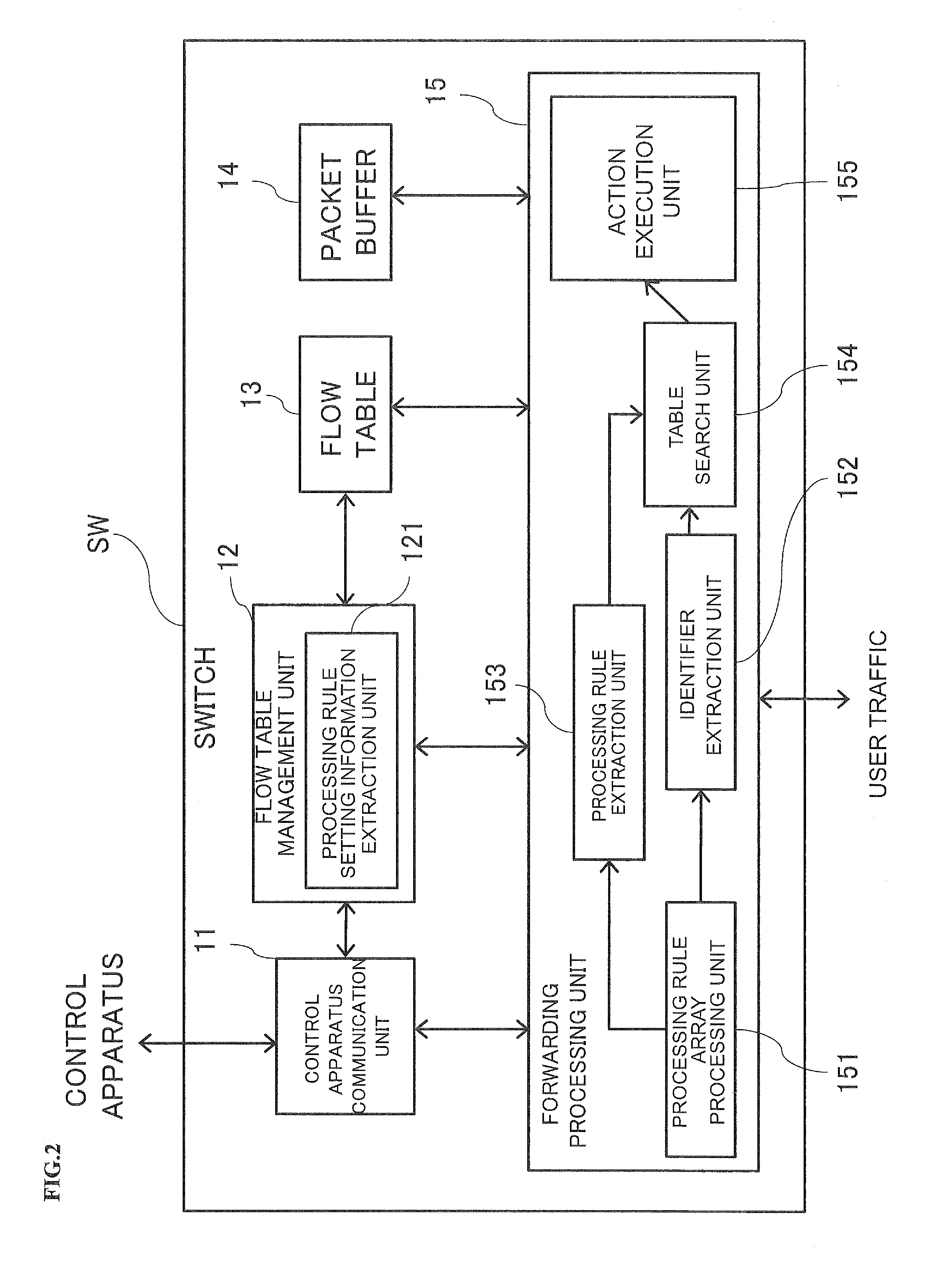
[0059]Each of the switches SW1-SW5 refers to a first rule for a packet processing to be executed by the switch in an array of processing rules included in a packet, and processes the packet according to the first rule. If the packet includes a predetermined identifier, each of the switches SW1-SW5 receives a packet processing to be executed by the switch and t...
second exemplary embodiment
[0086]A communication system according to a second exemplary embodiment will be described with reference to the drawings. The communication system according to the present exemplary embodiment includes a plurality of switches, among which a hub switch connected to the other plurality of switches is included. FIG. 7 is a block diagram showing a configuration of a communication system according to the present exemplary embodiment.
[0087]With reference to FIG. 7, the communication system according to the present exemplary embodiment includes a control apparatus 30 and eight switches SW1-SW8. Hosts A-C communicate via the switches SW1-SW8. The switch SW5 is a hub switch connected to a plurality of switches (four switches SW3, SW4, SW6 and SW7 in FIG. 7). Although FIG. 7 is illustrated in a simplified manner, the control apparatus 30 is connected to all the switches SW1-SW8.
[0088]FIG. 7 illustrates the control apparatus 20, eight switches SW1-SW8, and three hosts A-C as an example. Only t...
third exemplary embodiment
[0099]A communication system according to a third exemplary embodiment will be described with reference to the drawings. Although there is no hub switch in the communication system of the present exemplary embodiment, this communication system includes a switch having a particular feature or role such as a switch on which more traffic volume is concentrated than the other switches. FIG. 10 is a diagram showing an example of a configuration of a communication system according to the present exemplary embodiment.
[0100]With reference to FIG. 10, a control apparatus 40, seven switches SW1-SW7, and hosts A-D that communicate via the switches SW1-SW7 are illustrated. Although FIG. 10 is illustrated in a simplified manner, the control apparatus 40 is connected to all the switches SW1-SW7.
[0101]FIG. 10 illustrates one control apparatus 40, seven switches SW1-SW7, and four hosts A-D as an example. However, the number of these apparatuses included in the communication system is not limited to...
PUM
 Abstract
Description
Claims
Application Information
 - R&D
- Intellectual Property
- Life Sciences
- Materials
- Tech Scout
- Unparalleled Data Quality
- Higher Quality Content
- 60% Fewer Hallucinations
Browse by: Latest US Patents, China's latest patents, Technical Efficacy Thesaurus, Application Domain, Technology Topic, Popular Technical Reports.
© 2025 PatSnap. All rights reserved.Legal|Privacy policy|Modern Slavery Act Transparency Statement|Sitemap|About US| Contact US: help@patsnap.com


