Optical path-changing member

a technology of optical path and optical path, applied in the field of optical path change member, can solve the problem of difficult to change the optical path of incident light to the optimum direction, and achieve the effect of high-precision optical path chang

Active Publication Date: 2013-10-10
THE FUJIKURA CABLE WORKS LTD
View PDF2 Cites 34 Cited by
  • Summary
  • Abstract
  • Description
  • Claims
  • Application Information

AI Technical Summary

Benefits of technology

[0019]According to the present invention, since the first lens and the second lens are formed in the light incidence and emission surface, even in a case where a shift occurs in a direction of incident light, a direction of an optical path can be maintained in a desired direction by the two lenses.
[0020]Further, since both the first lens and the second lens are formed in the member main body, the relative positions of the two lenses do not change, and therefore, a highly accurate optical path change is possible.

Problems solved by technology

In the above-described optical path-changing members, since the reflection surface has the form of a flat slope, there is a problem in that it is difficult to change an optical path of incident light to an optimum direction.

Method used


Image

  • Optical path-changing member
  • Optical path-changing member
  • Optical path-changing member

Examples


first embodiment

[0029]Hereinafter, a first embodiment of the present invention will be described in detail based on the drawings.

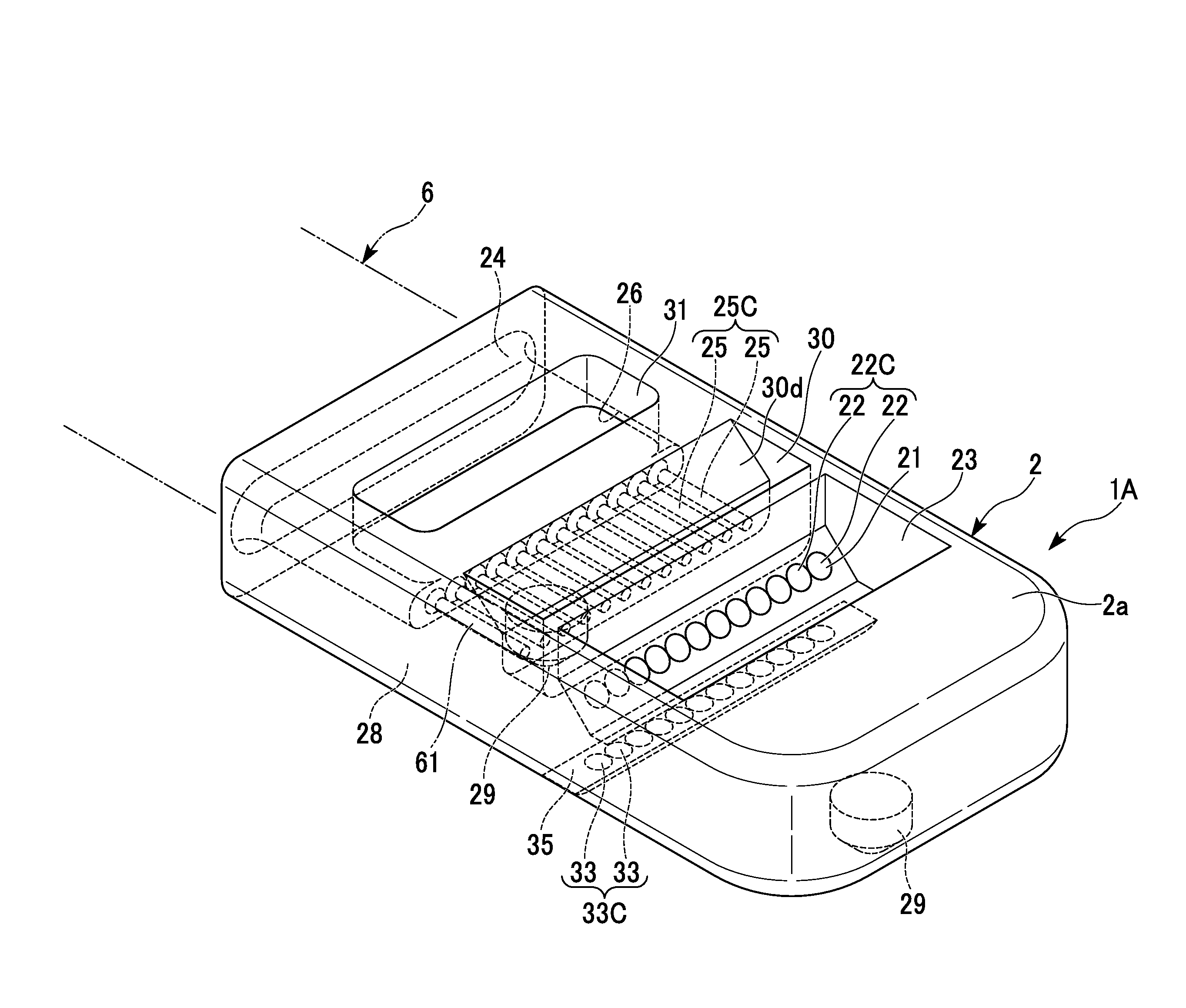
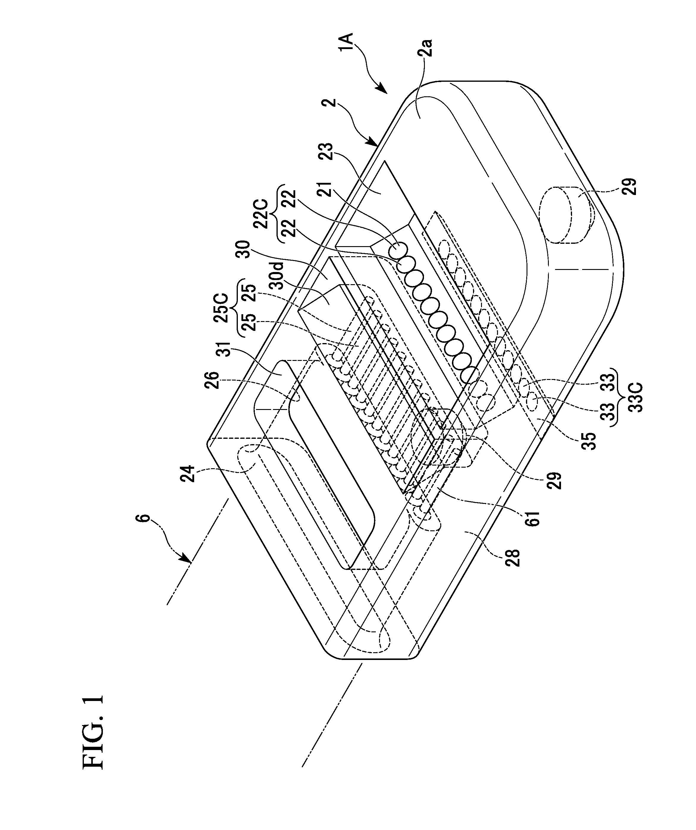
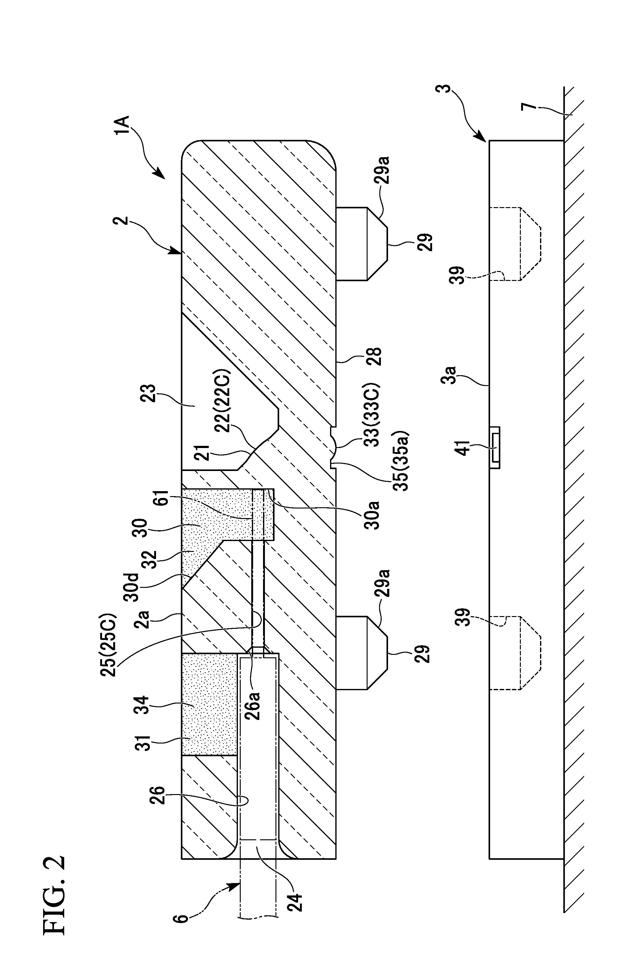
[0030]FIG. 1 is a perspective view of an optical path-changing member 1A of the first embodiment related to the present invention. FIG. 2 is a cross-sectional view of the optical path-changing member 1A. FIG. 3 is an enlarged cross-sectional view of the optical path-changing member 1A.

[0031]In the following description, a leading end direction (the right direction in FIG. 2) of a multi-core optical fiber 6 is sometimes referred to as the front and the opposite direction (the left direction in FIG. 2) thereto is sometimes referred to as the rear. Further, the front-back direction is a direction of an optical axis of the multi-core optical fiber 6.

[0032]As shown in FIGS. 1 and 2, a member main body 2 constituting the optical path-changing member 1A is provided at a terminal of the multi-core optical fiber 6, and the member main body 2 is installed to face an optical module ...

second embodiment

[0088]FIG. 4 is a perspective view of an optical path-changing member 113 of a second embodiment related to the present invention. FIG. 5 is a cross-sectional view of the optical path-changing member 1B. FIG. 6 is an enlarged cross-sectional view of the optical path-changing member 113.

[0089]As shown in FIGS. 4 and 5, optical fiber insertion holes 25 (25a and 25b) and first lenses 22 (22a and 22b) of the optical path-changing member 1B are two-dimensionally arranged so as to form a plurality of stages.

[0090]The optical fiber insertion holes 25 (25a and 25b) form a plurality of stages 25A and 25B (optical fiber insertion hole rows) that are made by arranging a plurality of optical fiber insertion holes 25 side by side in a lateral direction, and the first lenses 22 (22a and 22b) form a plurality of stages 22A and 22B that are made by arranging a plurality of first lenses 22 side by side in a lateral direction.

[0091]The optical fiber insertion holes 25 and the first lenses 22 are arra...

third embodiment

[0108]FIG. 7 is a perspective view of an optical path-changing member 1C of a third embodiment related to the present invention. FIG. 8 is a cross-sectional view of the optical path-changing member 1C.

[0109]As shown in FIGS. 7 and 8, optical fiber insertion holes 125 (125a and 125b) and first lenses 122 (122a and 122b) are two-dimensionally arranged so as to form a plurality of stages. The first lenses 122 (122a and 122b) form a plurality of stages 122A and 122B that are made by arranging a plurality of first lenses 122 side by side in a lateral direction.

[0110]The optical fiber insertion holes 125 and the first lenses 122 are arranged in two stages to correspond to the multi-core optical fibers 6 having a two-stage configuration.

[0111]When viewed from the direction of the optical axis of the light, positions of the optical fiber insertion holes 125 correspond to positions of the first lenses 122. Here, therefore, the embodiment will be described with reference to the positions of t...


PUM


Abstract

An optical path-changing member comprises a member main body which is made of a transparent material and in which a reflection section optically connecting the optical fiber to the light input and output end is formed, wherein the reflection section is a first lens having a concave shape when viewed from an incident direction and making light incident on the inside of the member main body from one of the optical fiber and the light input and output end be internally reflected in the member main body and directed to the other of the optical fiber and the light input and output end, a second lens having a convex shape toward the optical component is formed in a light incidence and emission surface of the member main body, that faces the optical component.

Description

CROSS REFERENCE TO RELATED APPLICATIONS[0001]Priority is claimed on Japanese Patent Application No. 2012-088861, filed on Apr. 9, 2012, and Japanese Patent Application No. 2013-037952, filed on Feb. 27, 2013, the contents of which are incorporated herein by reference.BACKGROUND OF THE INVENTION[0002]1. Field of the Invention[0003]The present invention relates to an optical path-changing member that is provided at a terminal of an optical transmission body such as an optical fiber. An optical path-changing member is an optical component for changing a direction of an optical path between an optical fiber and a light input and output end provided at a substrate, thereby optically connecting the optical fiber and the light input and output end.[0004]2. Description of Related Art[0005]In recent years, a method to fix an optical connector assembled to a leading end portion of an optical fiber wired along a substrate on which an optical element such as a light-emitting element such as a s...

Claims


Application Information

Patent Timeline
Patent Type & Authority Applications(United States)
IPC IPC(8): G02B6/32
CPCG02B6/32G02B6/4214G02B6/4249G02B6/4239G02B6/4244G02B6/423
Inventor NISHIMURA, AKITONUMATA, SHOTA
Owner THE FUJIKURA CABLE WORKS LTD
Why Eureka
Try Eureka