

Directional valve equipped with pressure compensation
- Summary
- Abstract
- Description
- Claims
- Application Information
AI Technical Summary
Benefits of technology
Problems solved by technology
Method used
Image

Examples
Embodiment Construction
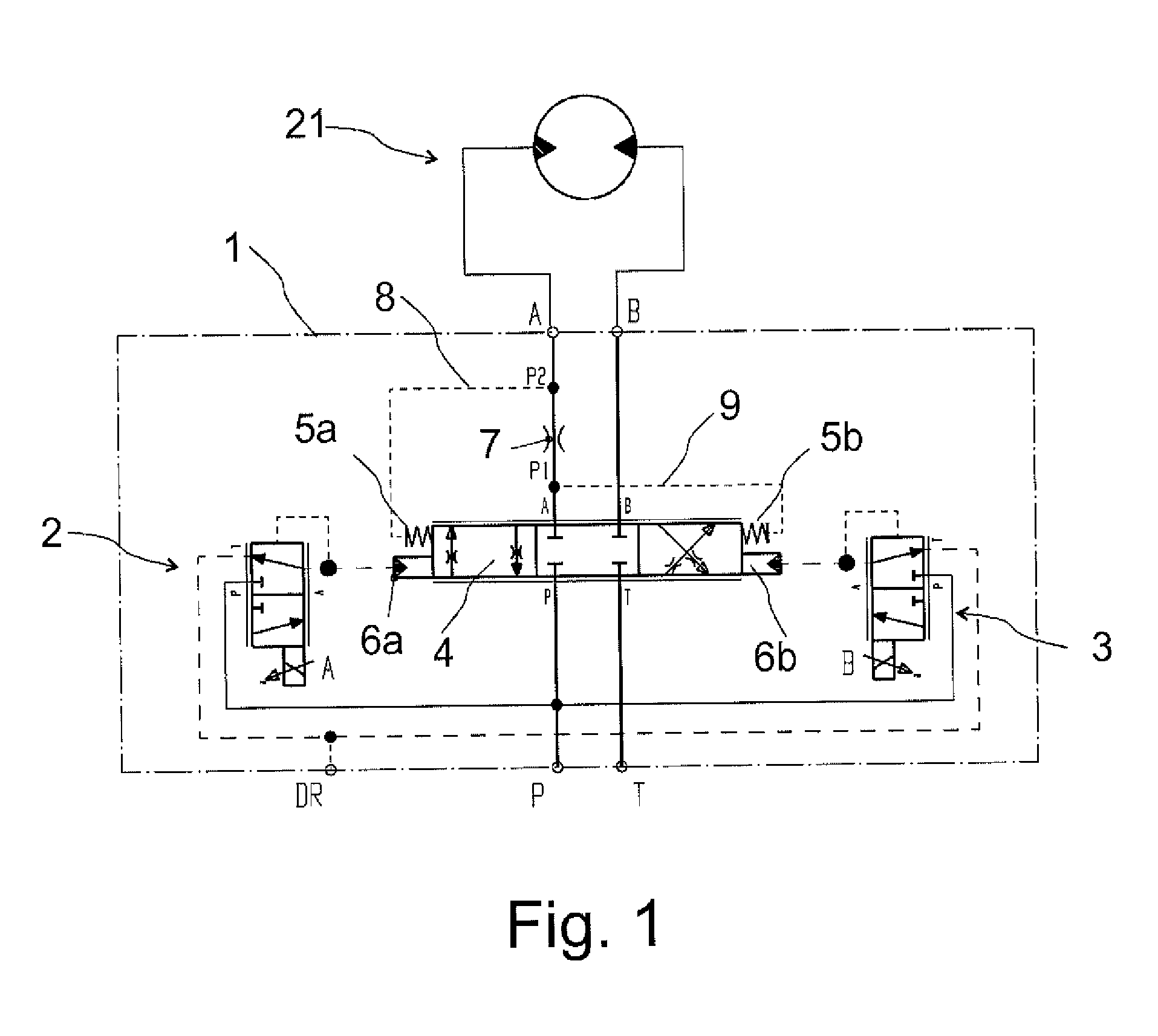
[0029]FIG. 1 shows, by means of graphic symbols of hydraulics and on the principle level, a directional valve in which the compensation according to the presented solution is applied. It is a valve that is particularly suitable for hydraulic oil or various flowing hydraulic fluids.
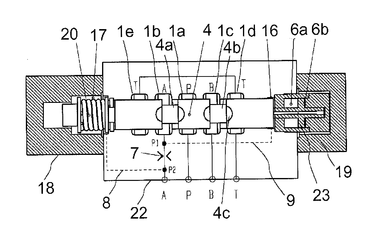
[0030]The valve 1 of FIG. 1 is a so-called 4 / 3 directional valve. The valve 1 comprises a spool 4 which is arranged, in the centre position of the valve 1, to close a pressure port P, a tank port T, and both work ports A and B. When the valve 1 is not under pilot control, the spool 4 is automatically set in the centre position, for example centered by means of springs 5a, 5b. The spool 4 is deviated from the centre position by applying forces generated by the pilot control. The spring force generated by the spring is used as a returning force and a counterforce for the force of the pilot control. Said force tends to move the spool to a desired position (e.g. the centre coupling position in FIG. 1), when th...
PUM
 Abstract
Description
Claims
Application Information