Cooling device

Inactive Publication Date: 2013-10-17
MOLEX INC
View PDF31 Cites 14 Cited by
  • Summary
  • Abstract
  • Description
  • Claims
  • Application Information

AI Technical Summary

Benefits of technology

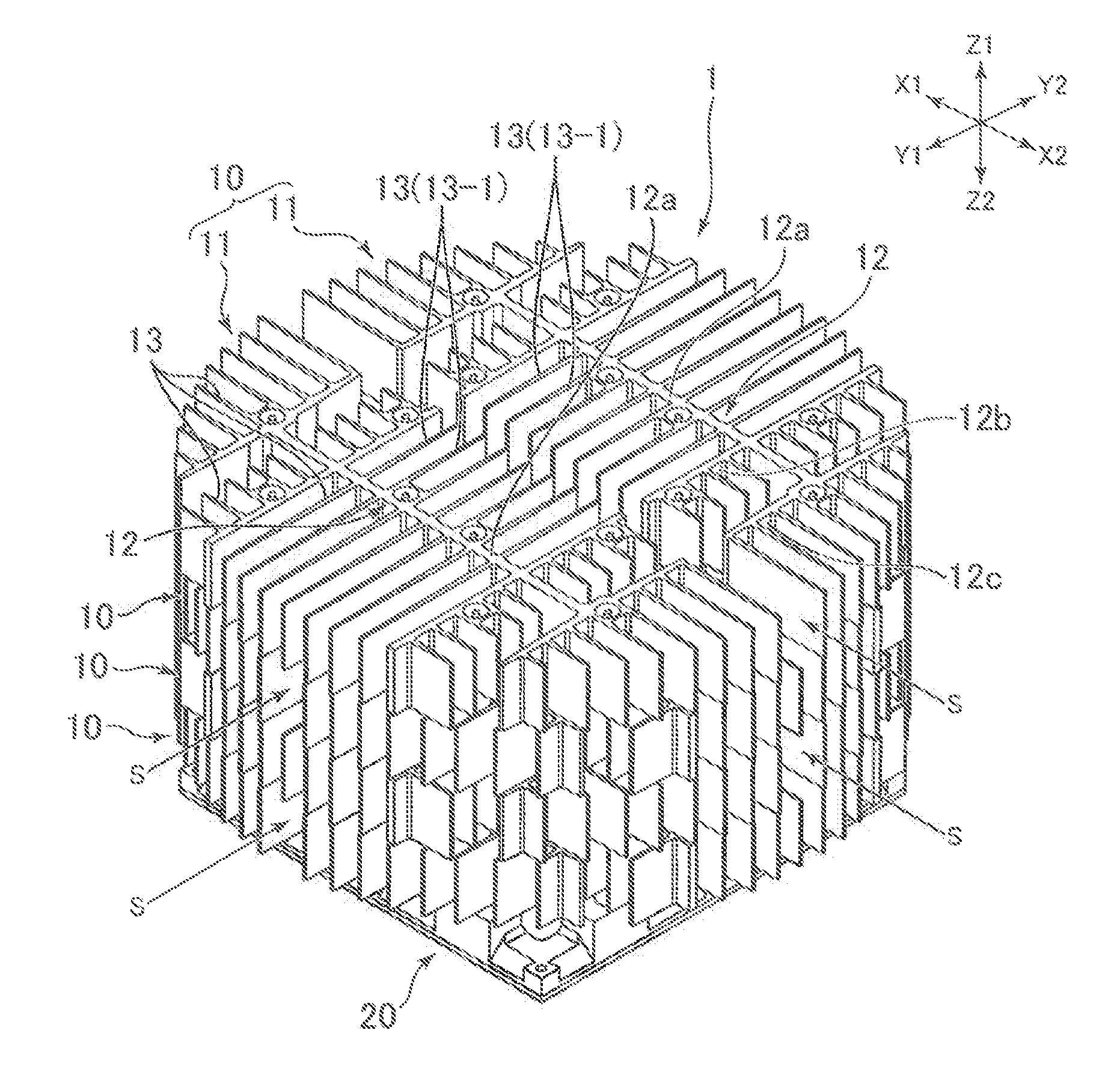
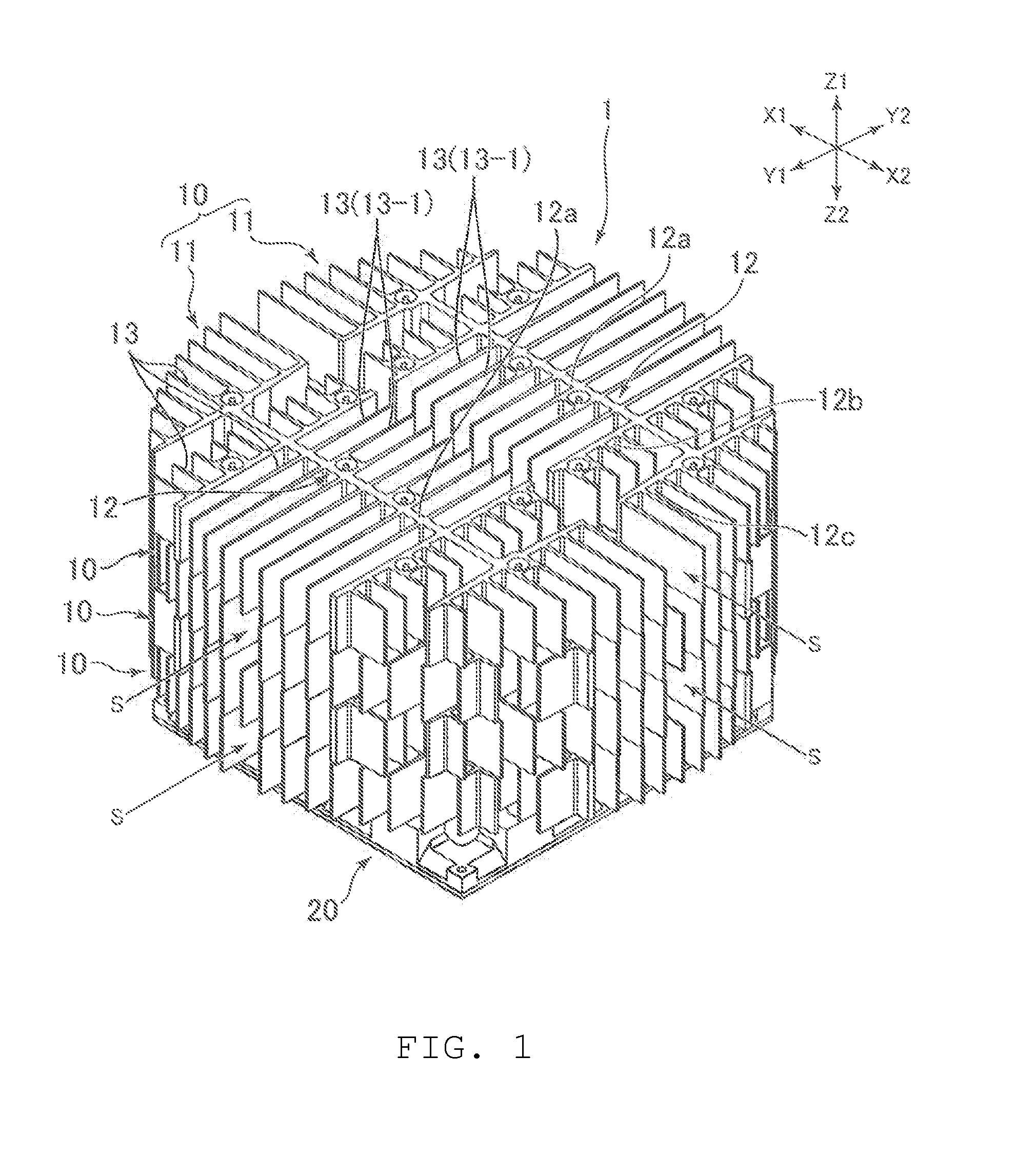
[0013]In one aspect of the Present Disclosure, each of the plurality of heat sinks may include a first half body having a support portion and a plurality of fins, and a second half body having a support portion and a plurality of fins. Here, the first half body and the second half body may be arranged symmetrically with respect to a straight line running along the heat-generating body. This allows the size of each heat sink to be increased. As a result, the cooling performance of the cooling device can be improved.
[0014]In one aspect of the Present Disclosure, an air passage may be formed between the first half body and the second half body, and the air passage may extend radially from the centerline running through the heat-generating body in the thickness dire

Problems solved by technology

Because it is difficult to increase the number of base pins using this structure, it is diff

Method used


Image

  • Cooling device
  • Cooling device
  • Cooling device

Examples


Embodiment Construction

[0024]While the Present Disclosure may be susceptible to embodiment in different forms, there is shown in the Figures, and will be described herein in detail, specific embodiments, with the understanding that the Present Disclosure is to be considered an exemplification of the principles of the Present Disclosure, and is not intended to limit the Present Disclosure to that as illustrated.

[0025]As such, references to a feature or aspect are intended to describe a feature or aspect of an example of the Present Disclosure, not to imply that every embodiment thereof must have the described feature or aspect. Furthermore, it should be noted that the description illustrates a number of features. While certain features have been combined together to illustrate potential system designs, those features may also be used in other combinations not expressly disclosed. Thus, the depicted combinations are not intended to be limiting, unless otherwise noted.

[0026]In the embodiments illustrated in ...


PUM


Abstract

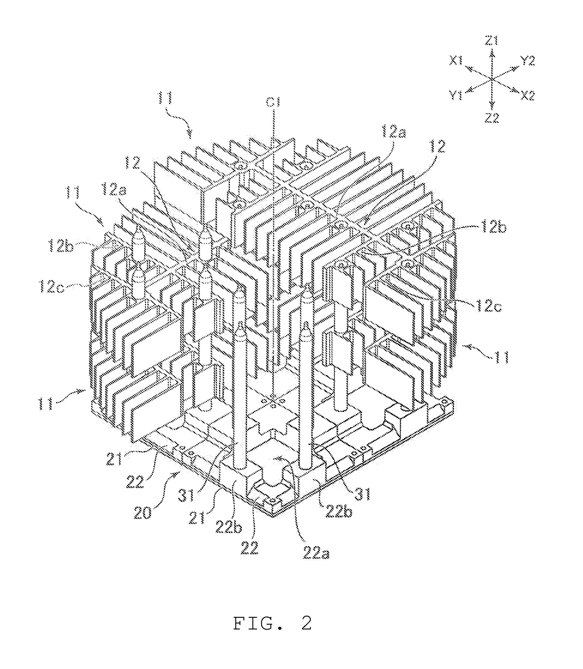
A heat-transferring member is mounted on one side of a circuit board. A heat sink is arranged farther away from the circuit board than the heat-transferring member in the thickness direction of the circuit board. The heat sink has a plurality of fins each extending in the direction of the circuit board and separated from each other by a space. Also, the heat sink includes a support portion extending in the direction of the plurality of fins and supporting the plurality of fins. A plurality of heat pipes is connected to the heat-transferring member and separated from each other by a space, each extending in the thickness direction of the circuit board and connecting to the support portion.

Description

REFERENCE TO RELATED APPLICATIONS[0001]The Present Disclosure claims priority to prior-filed Japanese Patent Application No. 2012-094163, entitled “Cooling Device,” filed on 17 Apr. 2012 with the Japanese Patent Office. The content of the aforementioned Patent Application is incorporated in its entirety herein.BACKGROUND OF THE PRESENT DISCLOSURE[0002]The Present Disclosure relates, generally, to a cooling device including a heat sink.[0003]A cooling device has been disclosed in Japanese Patent Application No. 2008-134115, which is used to radiate the heat of a heat-generating body in an electronic device. In this cooling device, a plurality of overlapping heat sinks (comb-shaped fins in the '115 Application) are arranged, and these are connected by a column-shaped base pin which transfers the heat.[0004]In the '115 Application, a plurality of fins extend radially from a single base pin in each heat sink. Because it is difficult to increase the number of base pins using this structu...

Claims


Application Information

Patent Timeline
IPC IPC(8): F28F3/02
CPCF28F3/02F28D15/0275F28F1/12F28D2021/0028H05K7/20418
Inventor TAKETOMI, KOUSUKEFUKUNAGA, RINKOU
Owner MOLEX INC
Why Eureka
Try Eureka