
Downhole tool for use in a drill string

Active Publication Date: 2013-10-17
SAUDI ARABIAN OIL CO
View PDF7 Cites 21 Cited by
  • Summary
  • Abstract
  • Description
  • Claims
  • Application Information

AI Technical Summary

Benefits of technology

The patent describes a downhole device that can connect to a drill string and help prevent blockages. The device includes a bypass sub with a relief valve assembly and a disconnect sub with upper and lower members that can be decoupled when the drill string remains motionless for a period of time. The device can also include a motion detector and controller to actuate the disconnect sub. The patent also describes an alternative embodiment of the downhole device that includes a bit and a downhole tool between the bypass sub and the drill string. Overall, the device helps improve safety and efficiency in drilling operations.

Problems solved by technology

If the well starts to produce while the drill string is plugged, flow cannot be circulated through the drill string to kill the well, thereby introducing the possibility of a blowout.
Another undesirable situation resulting from a plugged drill string is that the drill string can become stuck against the wellbore wall.

Method used


Image

  • Downhole tool for use in a drill string
  • Downhole tool for use in a drill string
  • Downhole tool for use in a drill string

Examples


Embodiment Construction

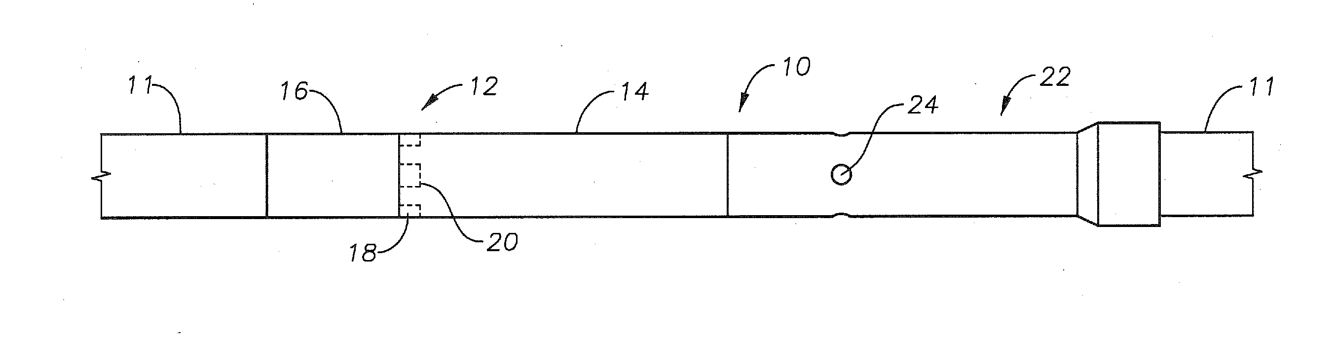
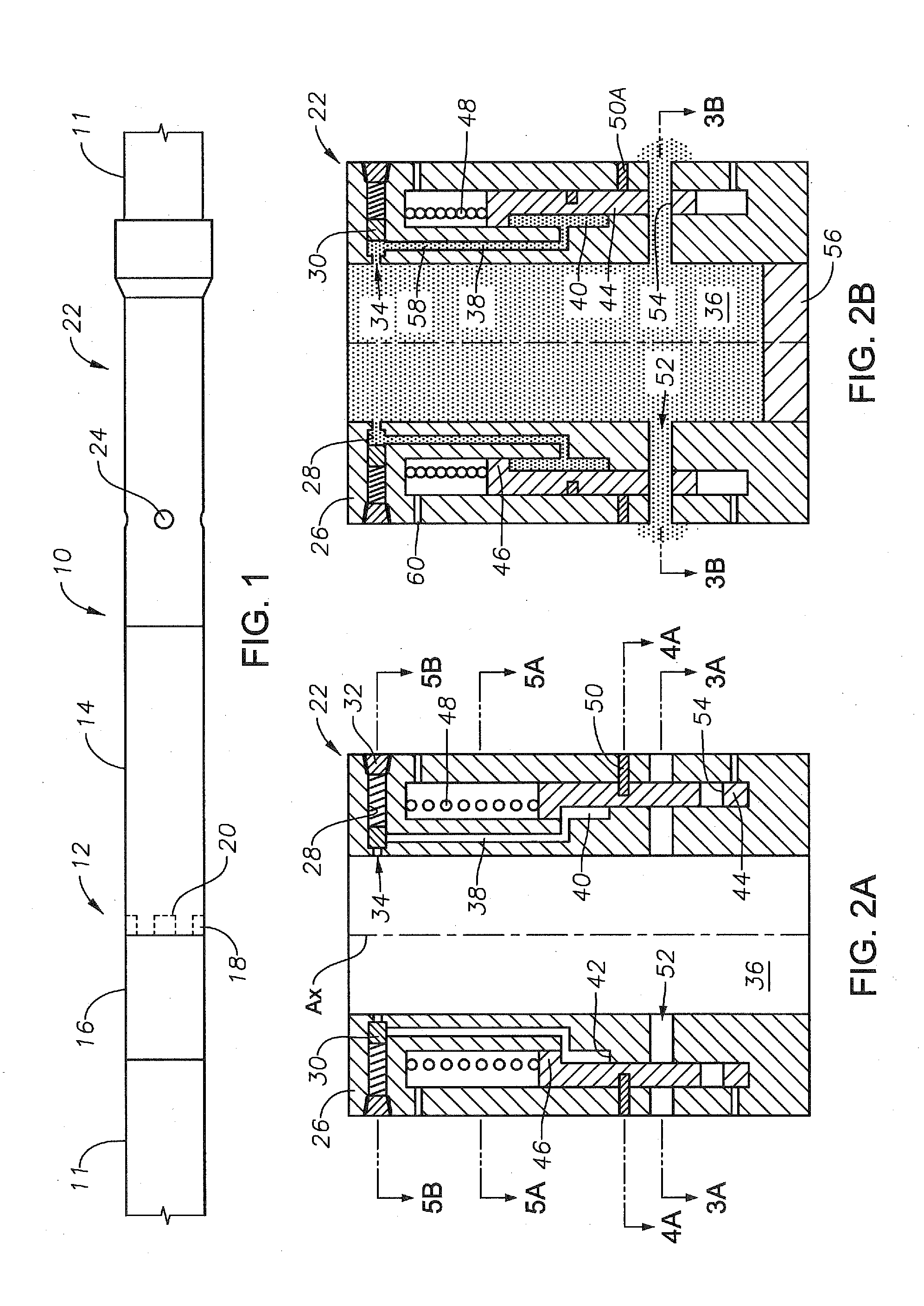
[0032]Shown in FIG. 1 is a side view of an elongated downhole tool 10 for use in a wellbore and for mitigating hazards that may occur during drilling. In one example embodiment, the downhole tool 10 is integrally included within a drill string 11. Included with the downhole tool 10 of FIG. 1 is a disconnect sub 12 shown having an upper member 14 and lower member 16, where upper member 14 selectively connects and disconnects from lower member 16. In the example of FIG. 1, the upper and lower members 14, 16 are generally annular and having a substantially circular outer surface. Clutch members 18 are provided on an upper end of the lower member 16 and are shown projecting into slots 20 formed on a lower end of the upper member 14. The clutch members 18 and slots 20 respectively circumscribe the lower member 16 and upper member 14. As the clutch members 18 and slots 20 are within the outer surface of the tool 10, they are illustrated by a dashed line. The rectangular outer periphery of...


PUM


Abstract

A downhole tool in a drill string for mitigating hazards of a blockage in an annulus of the drill string. The downhole tool can sense blockages and selectively recirculate flow from within the annulus back to surface. Further, the downhole tool is made up of segments that are selectively detachable from one another, so that the segments above the point of detachment are removable from a wellbore. The bypass assembly includes a sleeve in the downhole tool with openings in its side; when the annulus reaches a set pressure, the sleeve slides to a position so the openings register with ports formed through a side of the tool to allow bypass flow. A processor in the downhole tool senses movement of the string, and when the string is axially stationary more than a designated period of time, the processor emits signals to detach the segments.

Description

CROSS REFERENCE TO RELATED APPLICATIONS[0001]This application claims priority to and the benefit of co-pending U.S. Provisional Application Ser. No. 61 / 623,786, filed Apr. 13, 2012, the full disclosure of which is hereby incorporated by reference herein for all purposes.BACKGROUND OF THE INVENTION[0002]1. Field of the Invention[0003]The present invention relates to operations in a wellbore. More specifically, the invention relates to a system and method for mitigating hazards associated with use of a drill string.[0004]2. Description of the Related Art[0005]Hydrocarbon producing wellbores extend subsurface and intersect subterranean formations where hydrocarbons are trapped. The wellbores generally are created by drill bits that are on the end of a drill string, where a drive system above the opening to the wellbore rotates the drill string and bit. Cutting elements are usually provided on the drill bit that scrape the bottom of the wellbore as the bit is rotated and excavate materi...

Claims


Application Information

Patent Timeline
IPC IPC(8): E21B21/00E21B34/06
CPCE21B21/003E21B34/06E21B21/103E21B21/08E21B17/06
Inventor ZHOU, SHAOHUA
Owner SAUDI ARABIAN OIL CO
Features
  • Generate Ideas
  • Intellectual Property
  • Life Sciences
  • Materials
  • Tech Scout
  • Unparalleled Data Quality
  • Higher Quality Content
  • 60% Fewer Hallucinations
Learn More