Vehicle Elevator and Lift Therein

a technology for elevators and vehicles, applied in the direction of lifting frames, lifting devices, etc., can solve the problems of high vertical and horizontal forces on assembly elements, high degree of wear, etc., and achieve the effect of simple assembly, easy exchange or replacemen

Active Publication Date: 2013-10-17
STERTIL
View PDF2 Cites 5 Cited by
  • Summary
  • Abstract
  • Description
  • Claims
  • Application Information

AI Technical Summary

Benefits of technology

[0014]It is thus possible, instead of using diverse sets of assembly elements, to make use of a single set of assembly elements and associated bearing for the purpose of assembling the lift and the carrier, particularly by means of the rotation shaft. Only vertical loading forces are thus generated, this being favourable for the durability of the vehicle elevators according to the present invention. In addition, a great deal of time and money is saved in assembly, and errors in the alignment of sets of assembly elements can be avoided.
[0017]In a particularly advantageous preferred embodiment the vehicle elevator according to the present invention can have the feature that a slide block is arranged on the outer end of the post directed toward the carrier. Such a slide block can be enclosed in a profile or in a guide track which can be provided on the underside of the carrier for the purpose of guiding the movement of the relevant end of the post. Such a guide track will then be located at a distance from the line of assembly or the rotation shaft. It is however hereby possible to make a subassembly which substantially comprises only the lift. Other measures can however also be taken for this purpose. The slide blocks can in any case be inserted into the guide track and the rotation shaft having the at least two rotating components thereon can then be coupled to the carrier, preferably via the assembly elements to which the rotation shaft can then be coupled. Particularly when the guide track is here open at the outer end directed towards the line of assembly, a slide block can be readily inserted into the guide track at the relevant outer end of the post. A simple assembly can thus be realized. A lift can also be easily exchanged or replaced in a configuration according to the invention.
[0018]In yet another preferred embodiment one, or more than one, bearing block is arranged pre-mounted on either side of the rotation shaft. This also contributes toward being able to provide a subassembly which can form the lift for the vehicle elevator. A particular advantage of such a subassembly is that exchanging a lift can also take place in simple manner by detaching the rotation shaft and subsequently disassembling the vehicle elevator simply by sliding it out. A new lift can then be placed and mounted once again as subassembly so that the vehicle elevator can then be quickly taken into use again. Only the rotation shaft need be fixed again; the slide blocks need only be pushed or inserted into the guide tracks.
[0019]This further results in great freedom in assembling a vehicle elevator from one, or more than one, carrier and in herein choosing a lift with a desired lifting height suitable under the circumstances of use. Any random desired lift can then be mounted under any carrier.

Problems solved by technology

Such drawbacks are for instance high vertical and horizontal forces on the assembly elements.
There is moreover a further drawback that the sets of assembly elements are also aligned very precisely, this requiring great professional skill from for instance a welder for the purpose of arranging the assembly elements.
This results in a high degree of wear, since this wear is related to movement distances multiplied by the magnitude of the load.

Method used


Image

  • Vehicle Elevator and Lift Therein
  • Vehicle Elevator and Lift Therein
  • Vehicle Elevator and Lift Therein

Examples


Embodiment Construction

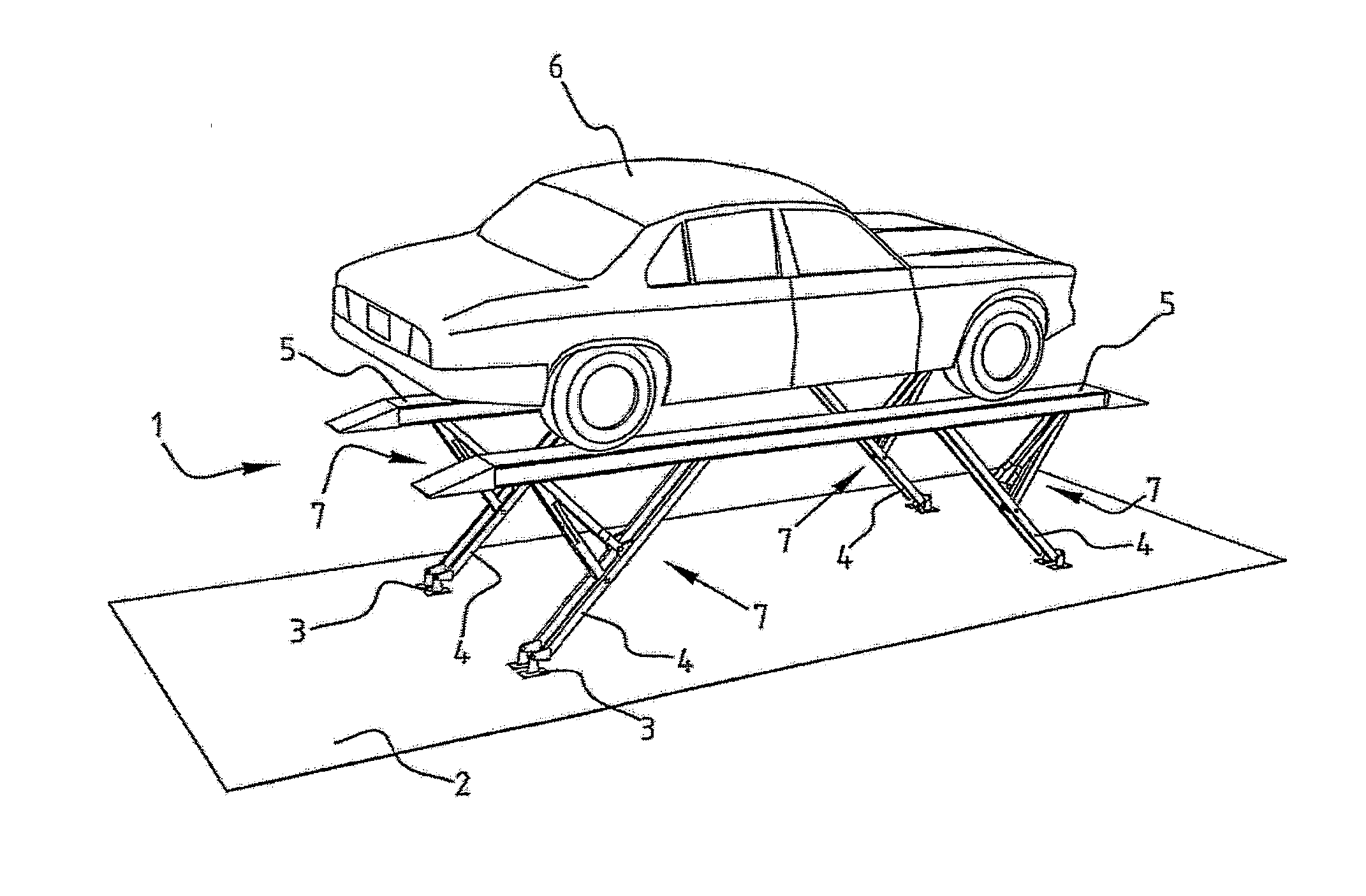
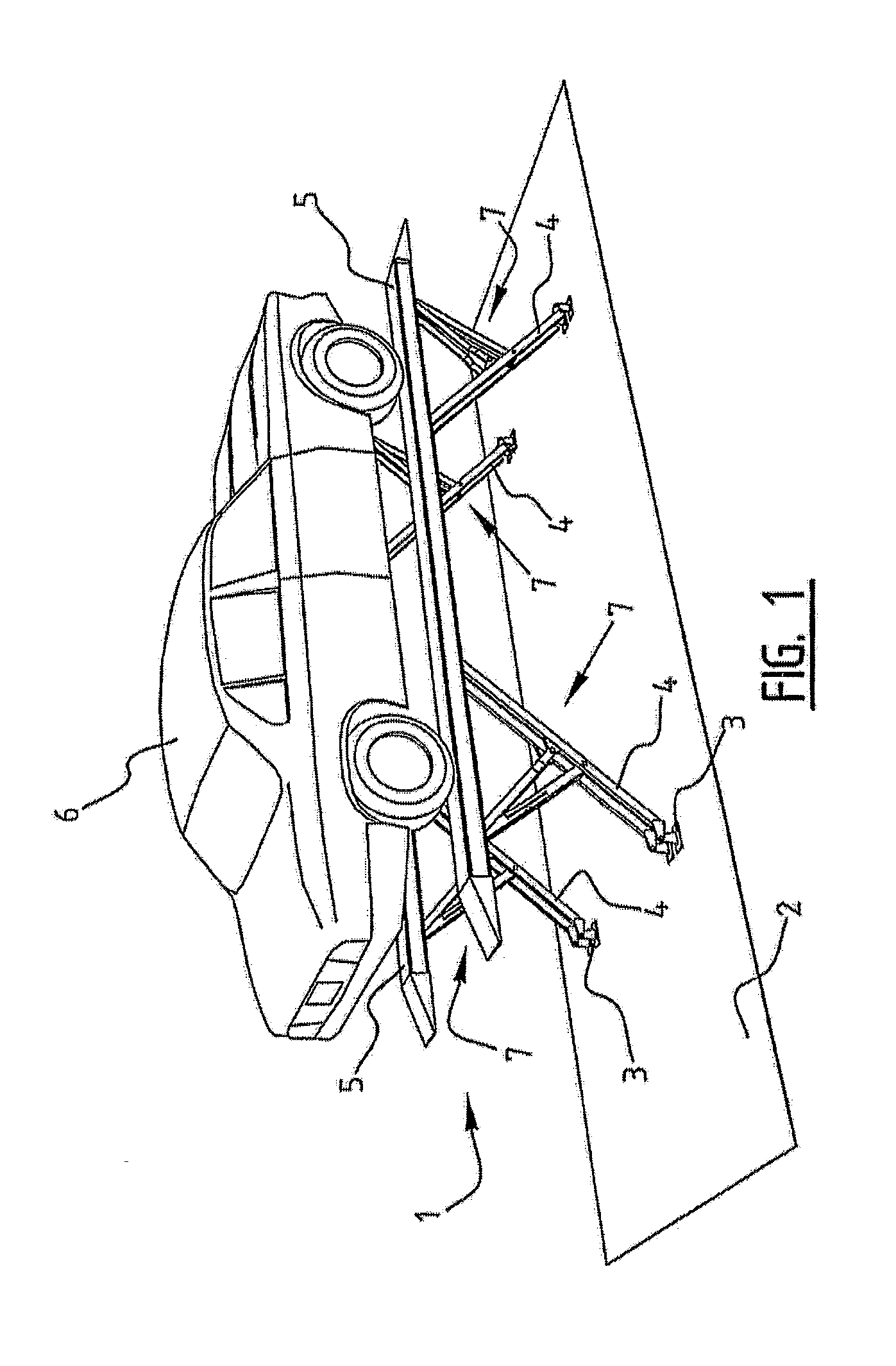
[0024]FIG. 1 shows a vehicle elevator 1. Vehicle elevator 1 is placed on a ground surface 2 using a number of feet 3.

[0025]A post 4 is mounted on each of the feet 3. Each post 4 comprises an assembly of two profiles 8 per post 4 with a small space between profiles 8. Posts 4 are arranged pivotally on feet 3. Pairs of posts 4 support in each case per couple a carrier designed as wheel track 5. Two wheel tracks 5 are thus provided in vehicle elevator 1.

[0026]A car 6 or other vehicle can drive onto wheel tracks 5 when wheel tracks 5 are situated on ground surface 2. Wheel tracks 5 must for this purpose be displaced downward relative to the situation shown in FIG. 1.

[0027]Use is made for this purpose of the lifts designed as half-scissor constructions 7.

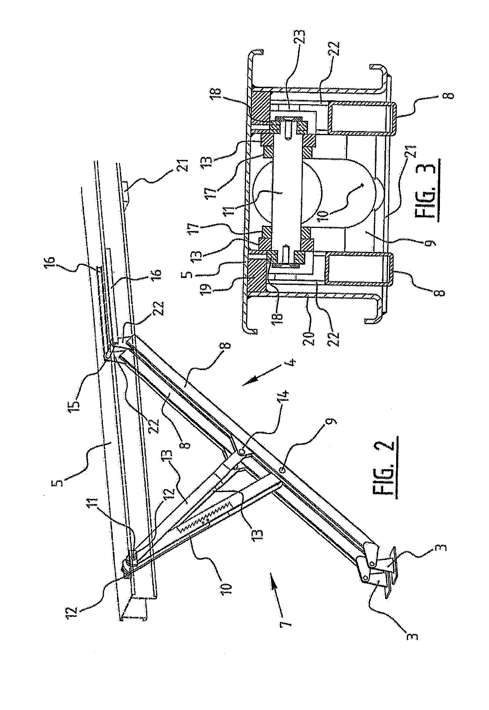
[0028]FIG. 2 shows a single half-scissor construction 7 together with a part of wheel track 5 which is shown in broken lines and under which the half-scissor construction 7 is arranged. The post 4 of the half-scissor construction 7 compr...


PUM


Abstract

The invention relates to a vehicle elevator, comprising: at least one carrier with a length direction for carrying a load thereon, such as a vehicle, and a lift under the carrier, which lift comprises at least two rotating components in a single line of assembly, wherein the rotating shaft extends along the line of assembly. The invention also relates to a lift for assembly in a vehicle elevator.

Description

CROSS REFERENCE TO RELATED APPLICATIONS[0001]This application is a continuation application of U.S. patent application Ser. No. 12 / 305,562, filed Feb. 24, 2009, entitled “Vehicle Elevator and Lift Therein”, which was the national stage of International Application No. PCT / NL2007 / 000147, filed Jun. 12, 2007, which claims priority to Dutch Patent Application No. 1032038, filed Jun. 21, 2006, all of which are hereby incorporated by reference in their entirety.BACKGROUND OF THE INVENTION[0002]1. Field of the Invention[0003]The present invention relates to a vehicle elevator and a lift in or for such a vehicle elevator.[0004]2. Description of Related Art[0005]It is known for such a vehicle elevator to comprise at least one carrier. Such a carrier has a length direction for carrying a load thereon. Vehicles can for instance be driven onto the carrier, or preferably carriers, of a vehicle elevator. The vehicles can then be displaced upward and then downward in order to create space under s...

Claims


Application Information

Patent Timeline
Patent Type & Authority Applications(United States)
IPC IPC(8): B66F7/06
CPCB66F7/0691B66F7/08B66F7/065
Inventor BERENDS, JAN
Owner STERTIL
Why Eureka
Try Eureka