Permanent magnet electric machine with two part or multi part permanent magnets

a permanent magnet, electric machine technology, applied in the direction of dynamo-electric machines, magnetic circuits characterised by magnetic materials, electrical apparatus, etc., can solve the problem of more cost-intensive use of magnet materials, and achieve the effect of high coercivity and higher remanen

Inactive Publication Date: 2013-10-17
ROBERT BOSCH GMBH
View PDF10 Cites 11 Cited by
  • Summary
  • Abstract
  • Description
  • Claims
  • Application Information

AI Technical Summary

Benefits of technology

[0010]In this case, the magnetic coercivity is understood to mean the magnetic field strength that is required for completely demagnetizing a ferromagnetic substance, with the result that the resulting total magnetic flux or the local magnetic flux density are equal to zero. The higher the coercivity, the better a magnet retains its magnetization when it is subjected to an opposing magnetic field.
[0013]However, as a result the costs of the electric machine increase considerably. In addition, owing to the high magnetic coercivity of the material used, although the risk of local demagnetization is reduced, a magnetic field strength produced by such permanent magnets can be lower than when using permanent magnets with a relatively low magnetic coercivity.
[0016]Owing to the provision of such a permanent magnet in at least two parts in an electric machine, magnetic properties produced by the permanent magnet elements can be matched to respective requirements prevailing locally within the electric machine. For example, high grade and therefore expensive magnet material with a high coercivity can be used in particular where it is required owing to the functional requirements of the electric machine. In regions with relatively low requirements, for example in terms of coercivity, correspondingly cheaper materials with higher remanence can be used.

Problems solved by technology

Costs for the magnet material of the permanent magnets are one of the greatest factors within the material costs.
In general, it can be assumed that the magnet material used is more cost intensive the higher the magnet coercivity of said material at high temperatures is.

Method used


Image

  • Permanent magnet electric machine with two part or multi part permanent magnets
  • Permanent magnet electric machine with two part or multi part permanent magnets
  • Permanent magnet electric machine with two part or multi part permanent magnets

Examples


Embodiment Construction

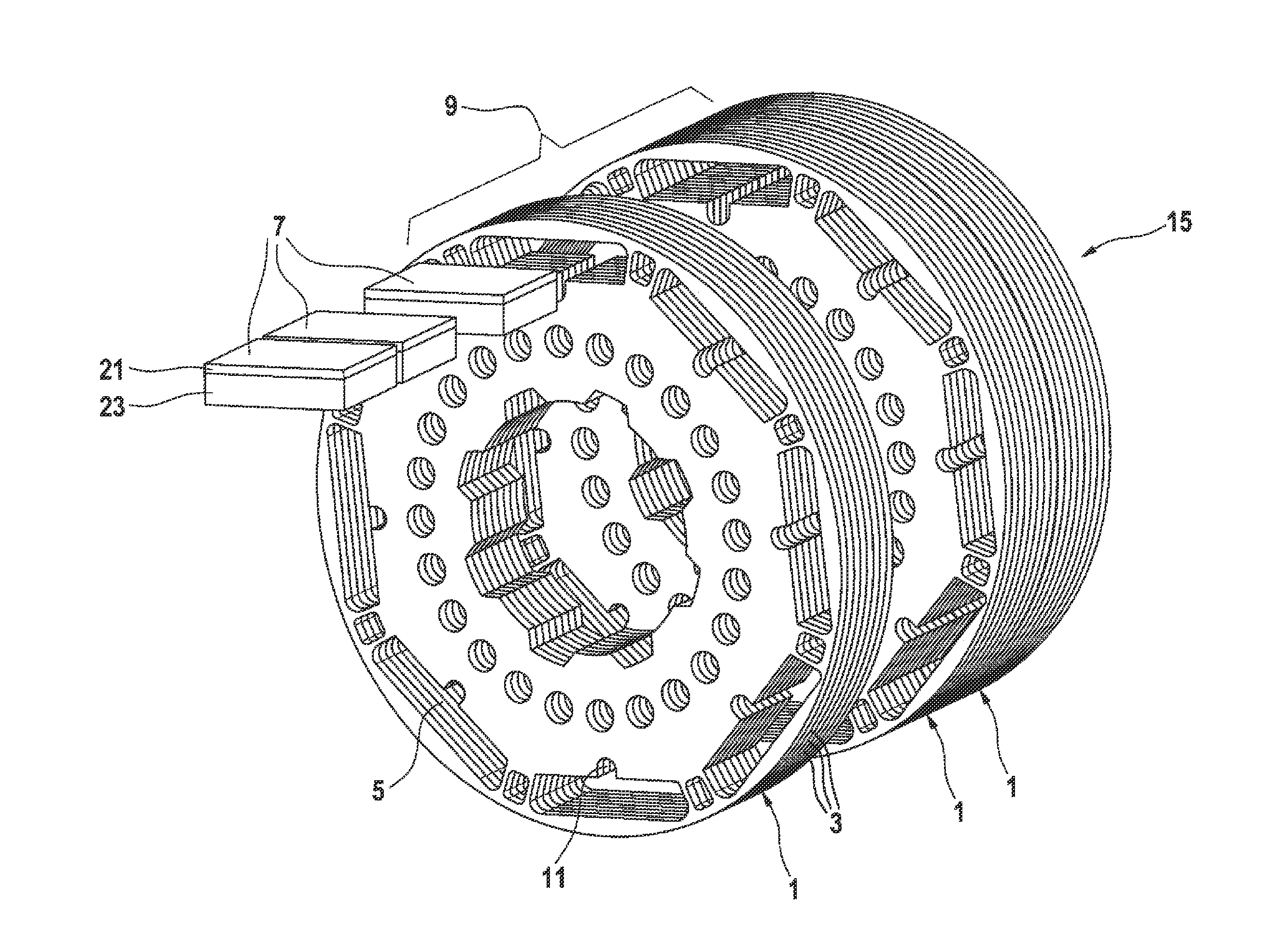
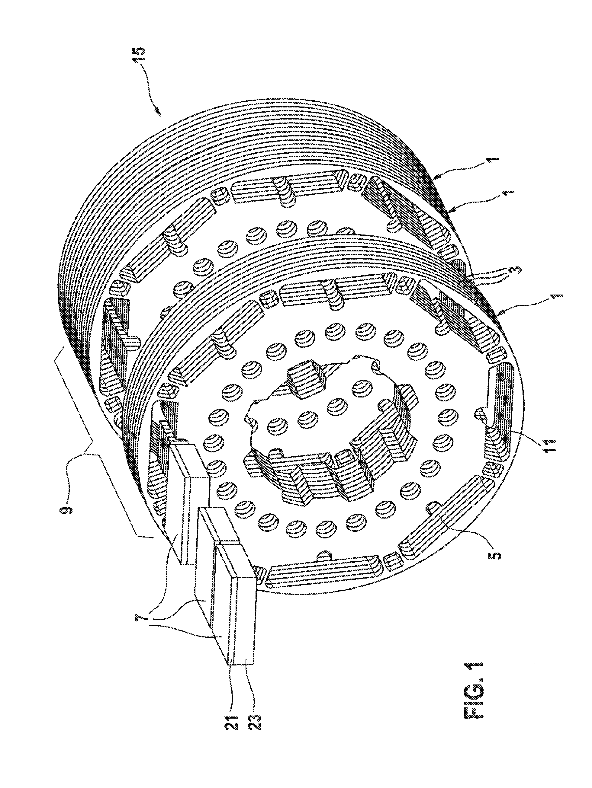
[0032]FIG. 1 shows a rotor body 9 of a rotor 15 for a permanent magnet electric machine. In order to improve clarity, the stator of the electric machine is not illustrated in FIG. 1. Given a typical design, the stator surrounds the rotor 15 in the form of a ring and has electromagnets which can be energized in a targeted manner, controlled by a controller of the electric machine.

[0033]The rotor body 9 comprises one or more laminate stacks 1, which are in turn formed by a large number of laminations 3 stacked one above the other in the form of thin stamped metal sheets. Substantially rectangular stamped out portions are provided in each of the laminations 3 in a region close to the outer circumference. The laminations 3 stacked one above the other form cutouts 5 within the rotor body 9 by virtue of the stamped out portions arranged in aligned formation.

[0034]During assembly of the rotor 15, square permanent magnets 7 are accommodated in the cutouts 5. Alternatively, square bodies con...


PUM


Abstract

A permanent magnet electric machine (2), in which permanent magnets (7) are arranged on a stator (13) and / or a rotor (15). In this case, a permanent magnet (7) has at least one first macroscopic permanent magnet element and one second macroscopic permanent magnet element (21, 23), wherein the permanent magnet elements (21, 23) are formed from different materials, which have different magnetic coercitivities.

Description

BACKGROUND OF THE INVENTION[0001]The present invention relates to a permanent magnet electric machine, in which strong permanent magnets are arranged on a stator and / or a rotor.[0002]Electric machines with a high power are often used, for example in the form of synchronous machines, as motors or generators in electric or hybrid drives for motor vehicles. Alternatively, electric machines are often used as generators in wind energy installations. The electric machine in this case has a fixed stator and a rotor, which can rotate relative to this stator about an axis of rotation.[0003]In order to be able to generate high forces with an electric machine when it is used as a motor or in order to be able to generate high electric currents with the electric machine when it is used as a generator, strong magnetic fields need to be produced within the electric machine. In permanent magnet electric machines, strong permanent magnets are provided on the rotor or on the stator for this purpose.[...

Claims


Application Information

Patent Timeline
Patent Type & Authority Applications(United States)
IPC IPC(8): H02K1/02
CPCH02K1/02H02K1/276H02K1/2766
Inventor GRACIA, MERCEDES HERRANZPLOEGER, ARMINMIEHLE, TILMANKIRCHHOFF, KARSTENHORN, JOHANNES
Owner ROBERT BOSCH GMBH
Why Eureka
Try Eureka