Apparatus Comprising Removable Light Source for Decorative Utility

Inactive Publication Date: 2013-10-17
RIFE CHERIE
View PDF14 Cites 23 Cited by
  • Summary
  • Abstract
  • Description
  • Claims
  • Application Information

AI Technical Summary

Benefits of technology

This patent is about a new jewelry setting that allows people to easily interchange ornaments without needing tools. It can be used for body jewelry, clothing, and accessories, and is durable and low-maintenance. The light source is simple and easy to control, and can be used for both decoration and lighting. Overall, this invention provides a cost-effective, user-friendly way to change jewelry settings.

Problems solved by technology

This can be quite limiting.
Generally, the user is manipulating loose gemstones, many of which are small and / or not colored (e.g. diamonds) and are therefore difficult to see and hold.
Thus, this kind of design increases the likelihood that an expensive gemstone can be lost.
However, it is difficult to devise a mechanism which provides the interchangeability without affecting the aesthetic nature of the jewelry.
However, a significant drawback of interchangeable jewelry has been the less than ease of use, less than secure mounting of the valuable feature unit onto the base unit, and the resulting unfortunate inadvertent loss of the valuable feature unit during normal wearing.
Furthermore, commercially available interchangeable jewelry apparatus often have interchanging apparatus for connecting the separable portions that is usually large and unsightly.
If the apparatus is too small or difficult to handle, most consumers will quickly become discouraged and discontinue use.
It is obvious that these two objectives are contradictory in nature.
In order to achieve both objectives, the prior art devices have traditionally been limited to use on jewelry articles having large ornaments with adequate surface area for mounting of the apparatus and for obstructing view of the apparatus.
These prior arts, however, have their own limitations.
Among the list of limitations are fragility, complexity of design, placement and interchangeability of the LED and / or PCB or other connectivity apparatus, unattractiveness, inability to market, non-versatile, costly to develop, costly to manufacture different ornamental attachments, and limited ornamental adaptability.
More specifically, most items involve a complex construction or electrical circuit which renders assembly difficult and expensive.

Method used


Image

  • Apparatus Comprising Removable Light Source for Decorative Utility
  • Apparatus Comprising Removable Light Source for Decorative Utility
  • Apparatus Comprising Removable Light Source for Decorative Utility

Examples


Embodiment Construction

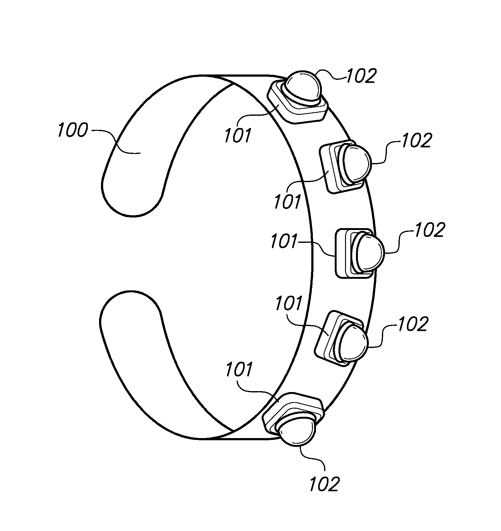
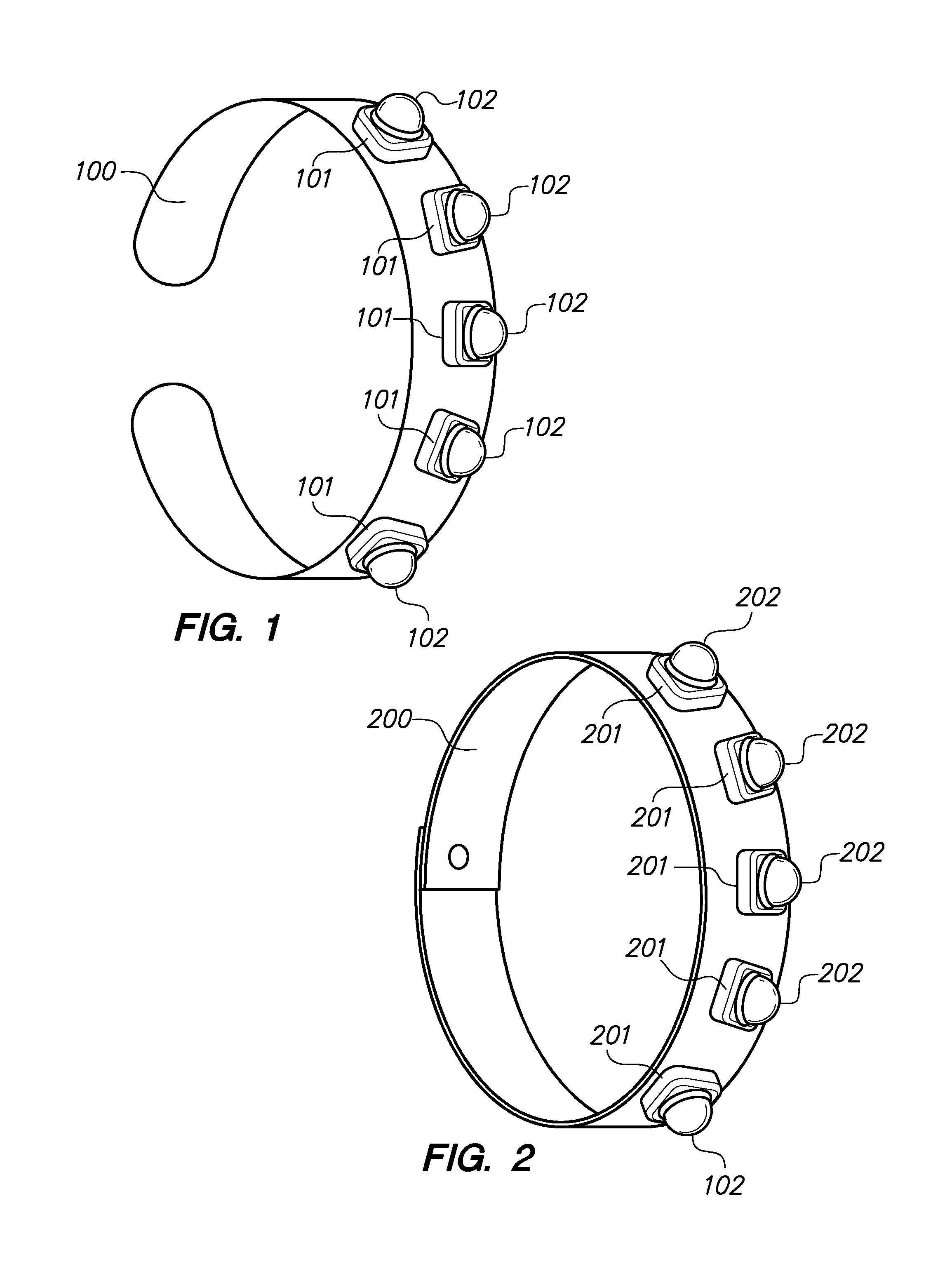
[0043]The present invention accomplishes these objectives and overcomes the disadvantages in the prior art. Since, in most cases, the apparatus will either be attached or connected to the human body directly in some fashion (e.g. a metal rod passed through the earlobe for an earring), or indirectly via a mechanism that furthers attaches to the human body (e.g. a connector to a necklace chain), it is possible that one of the interchangeable jewelry segments in a custom jewelry assembly can be an interchangeable jewelry base. It is also possible that the base portion can be a separate unit that can be attached to another article (e.g. attaching the base to a belt), upon which an ornament can then be attached.

[0044]The base portion preferably includes an engagement formation, and the ornament portion includes a complimentary engagement formation. When the engagement surfaces of the base and ornament portions are received in engagement, the ornamental surfaces thereof cooperatively merg...


PUM


Abstract

Apparatus for decorative utility comprising an ornament unit, a base unit, and a lighting unit, wherein the lighting unit comprises of a circuit board, power source such as battery, and at least one light source, such as a light emitting diode. The ornament unit is interchangeable, and can be disengaged and mounted onto the same or different base unit. The lighting unit may include one or more light sources, wherein the color and / or levels of intensity of the illumination can be modified and controlled.

Description

INCORPORATION BY REFERENCE[0001]This application claim the benefit of priority under 35 U.S.C. 119(e) to the filing date of U.S. provisional patent application No. 61 / 624,234 “Apparatus Comprising Removable Light Source for Decorative Utility” which was filed on Apr. 13, 2012, and which is incorporated herein by reference in its entirety.FIELD OF THE INVENTION[0002]The present invention relates generally to the field of jewelry and more specifically to apparatus for interchanging ornaments with interchanging light sources for a jewelry article. Particularly, the invention deals with movable jewelry wherein the ornaments for decoration displayed can be illuminated, positioned, and modified as desired by the user with certain prescribed possibilities.BACKGROUND OF THE INVENTION[0003]Jewelry pieces are conventionally permanent. In other words, once a jewel is fixed within a setting, the jewel and the setting may only be used or worn as a combined unit on one part of the body. In fact, ...

Claims


Application Information

Patent Timeline
IPC IPC(8): F21V21/08
CPCA44C15/0015A44C17/02A45C15/06F21L4/00F21V17/107
Inventor RIFE, CHERIE
Owner RIFE CHERIE
Why Eureka
Try Eureka