Wireless imaging system

a wireless imaging and wireless technology, applied in the field of anatomical imaging systems, can solve the problems of tissue damage, time-sensitive effect of a particular treatment, tissue oxygenation loss,

Inactive Publication Date: 2013-10-17
NEUROLOGICA CORP
View PDF4 Cites 118 Cited by
  • Summary
  • Abstract
  • Description
  • Claims
  • Application Information

AI Technical Summary

Benefits of technology

[0016]And there is provided a novel mobile CT machine with cordless and wireless capabilities, such that the novel CT machine does not require physical cabling to (i) provide the electrical power needed to operate the mobile CT scanner, and (ii) connecting the CT scanner to a workstation, hospital PACs system or other IT network.

Problems solved by technology

Strokes are caused by an abrupt interruption of the blood supply to the brain or spinal cord, thereby depriving the tissue of oxygen and resulting in tissue damage.
This is because the treatment for an ischemic stroke may be contra-indicated for the treatment for a hemorrhagic stroke and, furthermore, the effectiveness of a particular treatment may be time-sensitive.
However, current diagnosis times, i.e., the time needed to identify that the patient is suffering from a stroke and to identify the hemorrhagic or ischemic nature of the stroke, frequently exceeds this 3 hour window.
Unfortunately, in practice, the CT machine is typically located in the hospital's radiology department and the patient is typically received in the hospital's emergency room, and the “round-trip” time between the emergency room and the radiology department can frequently involve substantial delays, even in the best of hospitals.
As a result, the time spent in transporting the patient from the emergency room to the radiology department and then back again can consume critical time which can compromise proper treatment of the patient (e.g., it can prevent ischemic stroke victims from being timely treated with tPA).
However, if the CT scanner is to be highly mobile so that the CT scanner can be brought to the bedside of the patient, conventional physical cabling presents a significant problem, since it can interfere with the delivery of time-critical medical treatment and present a physical hazard to medical personnel focused on delivering such medical treatment.
This physical cabling would present a significant intrusion into the point of care, complicating the delivery of time-critical medical treatment and presenting a physical hazard to medical personnel working around the patient.

Method used


Image

  • Wireless imaging system
  • Wireless imaging system
  • Wireless imaging system

Examples


Embodiment Construction

The Mobile CT Imaging System in General

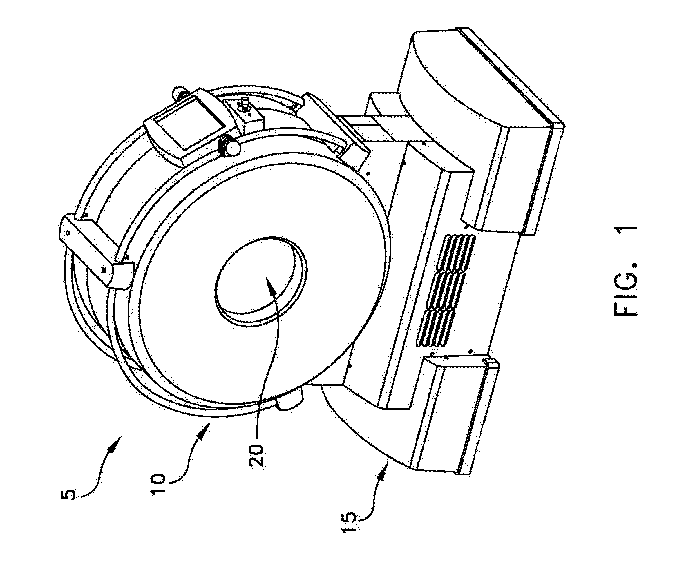
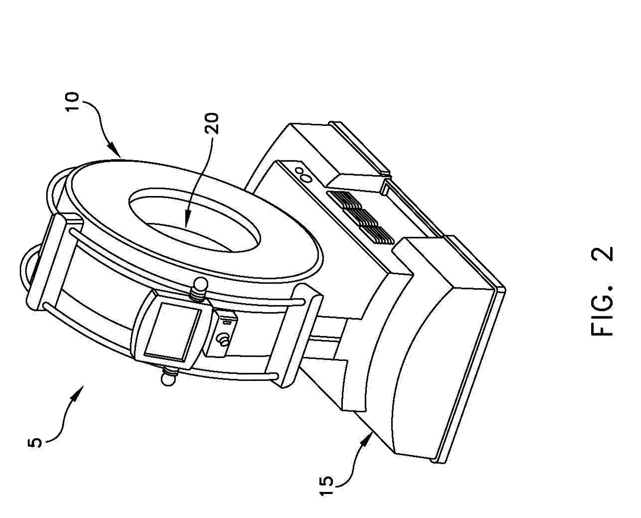
[0036]Looking first at FIGS. 1 and 2, there is shown a novel mobile CT imaging system 5 formed in accordance with the present invention. Mobile CT imaging system 5 generally comprises a torus 10 which is supported by a base 15. Torus 10 and base 15 together comprise a frame for mobile CT imaging system 5. A center opening 20 is formed in torus 10. Center opening 20 receives the patient anatomy which is to be scanned, i.e., the head of the patient when mobile CT imaging system 5 is to be used in stroke applications.

[0037]Looking next at FIG. 3, torus 10 generally comprises a X-ray tube assembly 25, an X-ray detector assembly 30, and a rotating drum assembly 35. X-ray tube assembly 25 and X-ray detector assembly 30 are mounted to the rotating drum assembly 35 in diametrically-opposing relation, such that the X-ray beam 40 (generated by X-ray tube assembly 25 and detected by X-ray detector assembly 30) is passed through the patient anatomy dispose...


PUM


Abstract

A wireless imaging system comprising:
    • a scanner for creating an image of an interior portion of an object;
    • a guidance system for using an image of an interior portion of an object to provide guidance to an individual with respect to the object;
    • the scanner comprising an on-board wireless communication unit, and the guidance system comprising an on-board communication unit, the on-board wireless communication unit of the scanner and the on-board communication unit of the guidance system being configured to wirelessly transfer images created by the scanner directly to the guidance system.

Description

REFERENCE TO PENDING PRIOR PATENT APPLICATION[0001]This patent application claims benefit of pending prior U.S. Provisional Patent Application Ser. No. 61 / 624,522, filed Apr. 16, 2012 by Eric Bailey for WIRELESS IMAGING SYSTEM (Attorney's Docket No. NEUROLOGICA-46 PROV), which patent application is hereby incorporated herein by reference.FIELD OF THE INVENTION[0002]This invention relates to anatomical imaging systems in general, and more particularly to wireless imaging systems.BACKGROUND OF THE INVENTION[0003]Strokes are currently the third leading cause of death in the United States, causing approximately 177,000 deaths per year, and strokes are currently the number one cause of long-term disability in the United States, currently affecting nearly 5 million people. Strokes are caused by an abrupt interruption of the blood supply to the brain or spinal cord, thereby depriving the tissue of oxygen and resulting in tissue damage.[0004]Strokes typically occur in one of two forms: (i) ...

Claims


Application Information

Patent Timeline
Patent Type & Authority Applications(United States)
IPC IPC(8): A61B6/00A61B6/03
CPCA61B6/563A61B6/032A61B6/4405A61B6/548A61B6/56
Inventor BAILEY, ERICDICKMAN, MATTHEWLIMOLI, MICHAEL
Owner NEUROLOGICA CORP
Why Eureka
Try Eureka