
Transducer impedance measurement for hearing aid

a technology of impedance measurement and hearing aid, which is applied in the field of hearing aids, can solve the problems of limiting the efficacy of the device, overly conservative device settings, and err on the side of the manufacturer or clinician

Active Publication Date: 2013-10-17
ST CROIX MEDICAL
View PDF4 Cites 19 Cited by
  • Summary
  • Abstract
  • Description
  • Claims
  • Application Information

AI Technical Summary

Benefits of technology

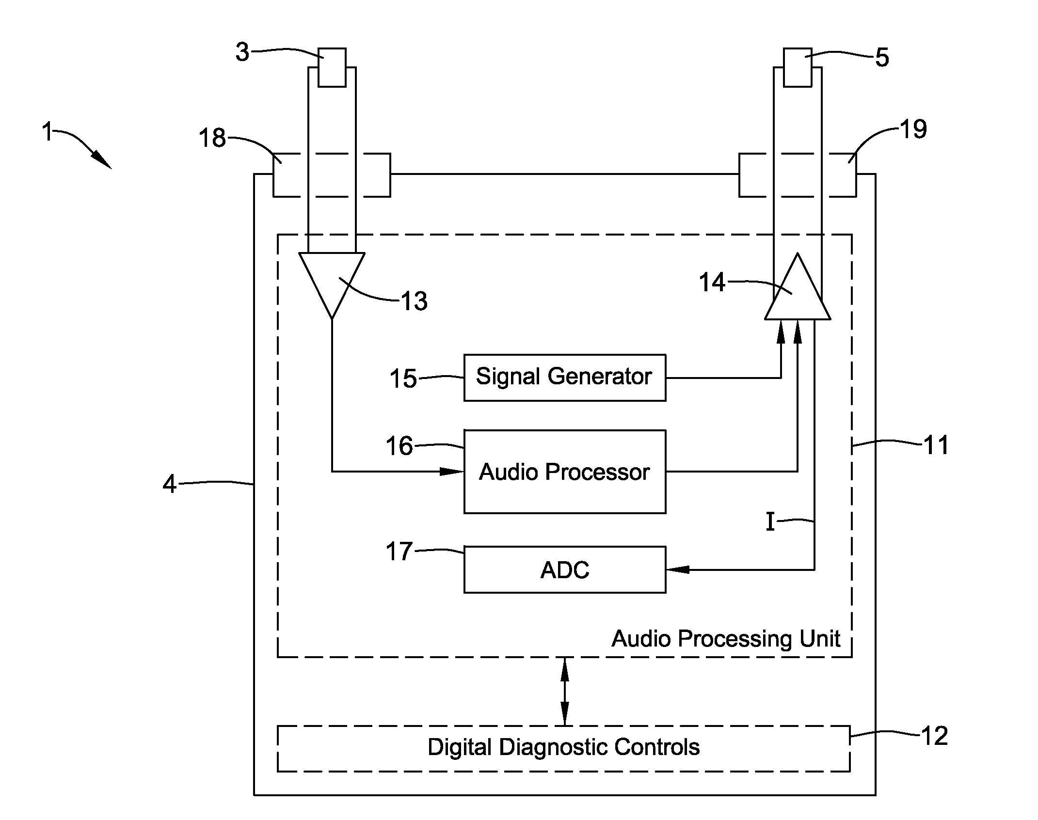
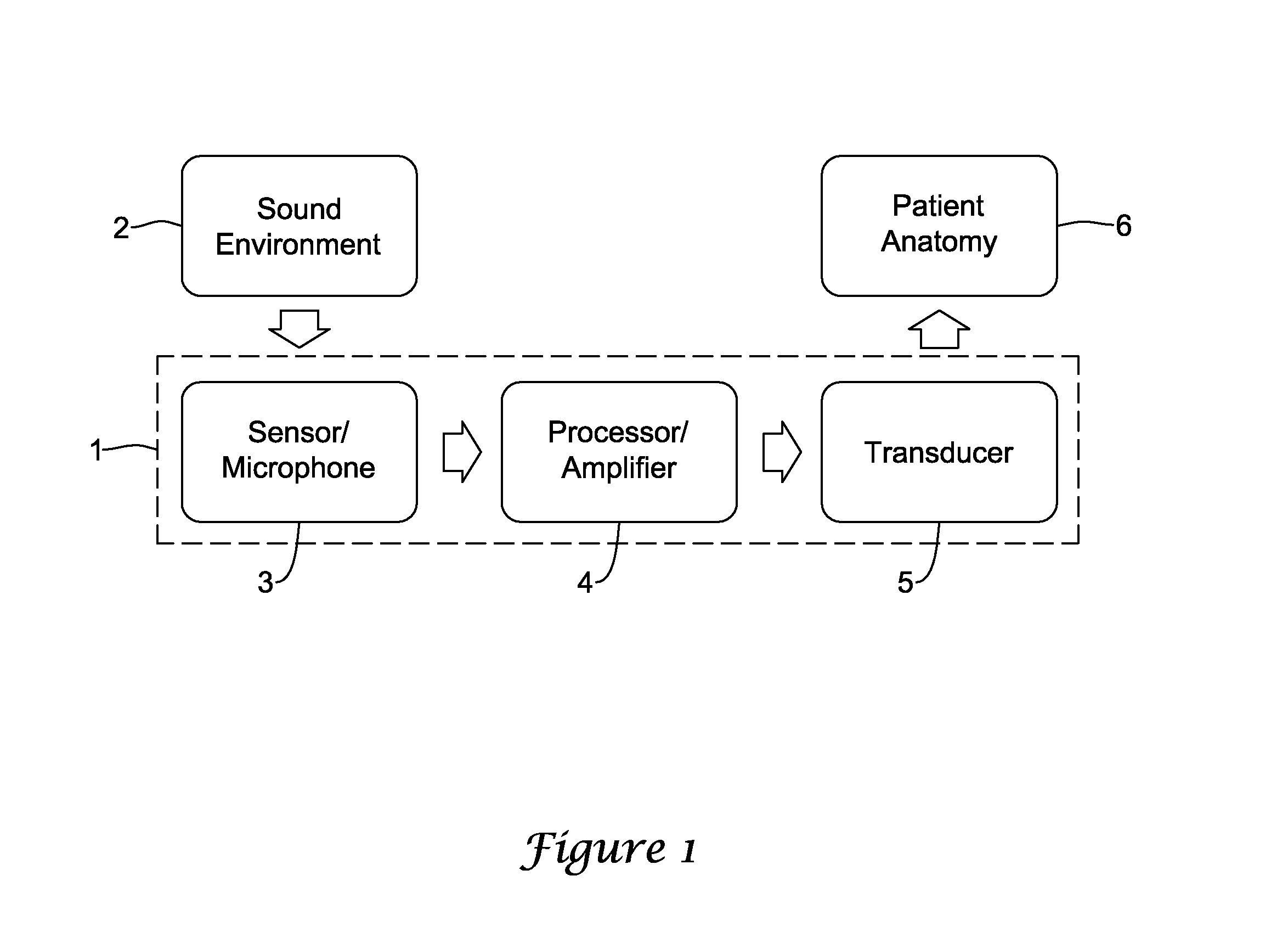
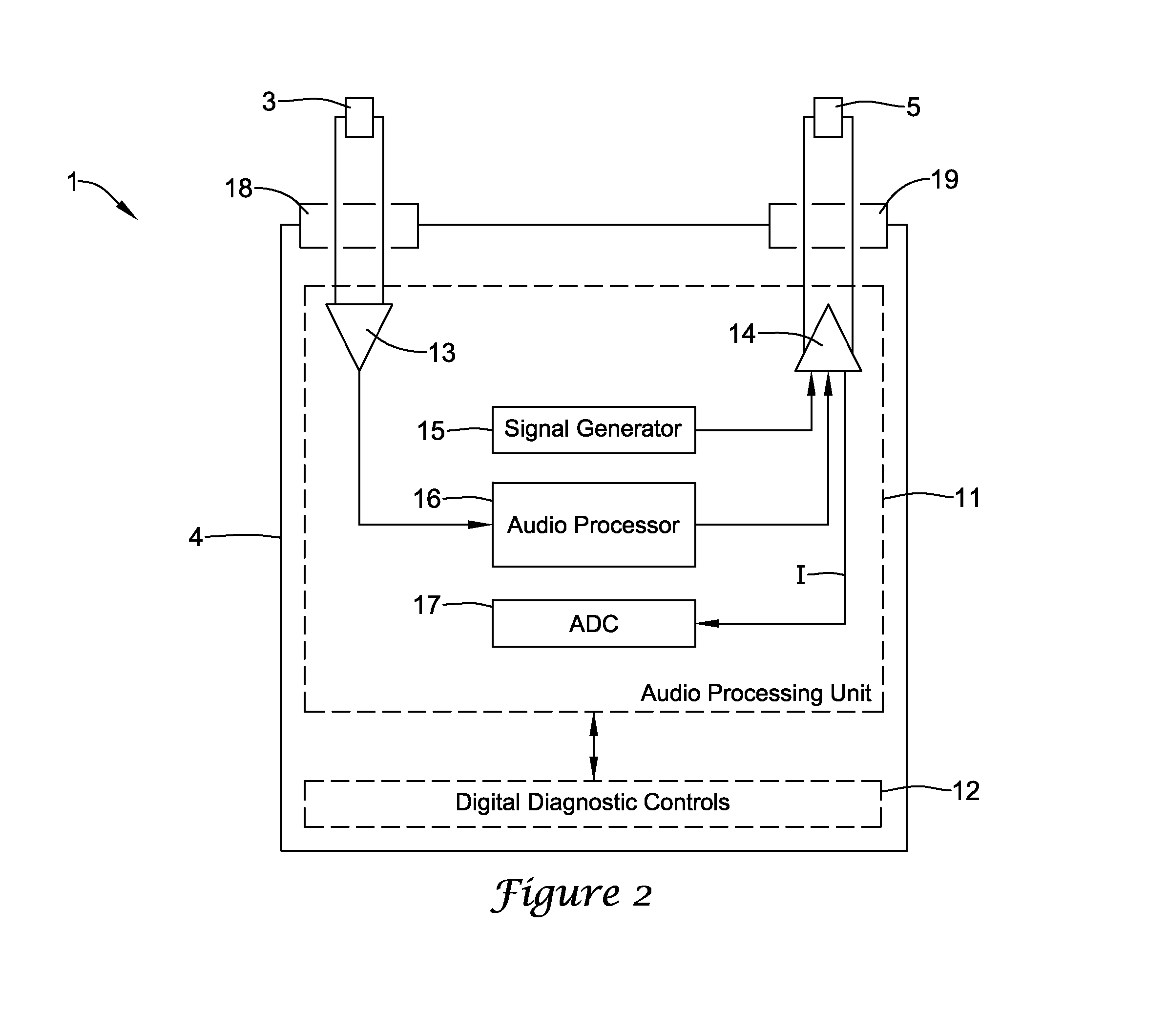
The invention is a hearing aid that includes a transducer and an amplifier. The hearing aid can stimulate the patient's anatomy in response to ambient sound and has a test mode at a predetermined test frequency. The amplifier produces a primary output signal at the test frequency, which is periodically scaled to produce a secondary output signal. The secondary output signal has a peak voltage and current that flows through the transducer. The impedance of the transducer at the test frequency is determined from the recorded voltage and current. This impedance is proportional to the steady-state voltage that is averaged over the one-sided secondary output current. The technical effect of the invention is to provide a hearing aid that can accurately measure the impedance of the transducer to ensure optimal performance.

Problems solved by technology

Without an accurate impedance measurement, the manufacturer or clinician may err on the conservative side when programming the device to ensure that the device does not cause anatomical damage in the worst case, or lowest impedance, circumstance.
This may lead to overly conservative device settings and may consequently unduly limit the efficacy of the device.
In any of these cases, the transducer could be damaged during shipping or during the surgical process of implantation.
The transducer may also fail after the surgical process is complete.
Despite these benefits, the removable electrical connections may come loose over time and may disconnect from the processor in the housing.

Method used


Image

  • Transducer impedance measurement for hearing aid
  • Transducer impedance measurement for hearing aid
  • Transducer impedance measurement for hearing aid

Examples


Embodiment Construction

[0020]For the purposes of this document, the term “hearing aid” is intended to mean any instrument or device designed for or represented as aiding, improving or compensating for defective human hearing and any parts, attachments or accessories of such an instrument or device.

[0021]A hearing aid is disclosed, which, in a test mode, can determine the impedance of the transducer that stimulates the anatomy of the patient. Impedance may be determined by simultaneous determination of the current flowing through the transducer and the voltage across the transducer. In some cases, the output amplifier of the hearing aid includes two outputs, with one being a scaled and / or summed replica of the other. The amplifier is driven with a periodic signal with a particular frequency and a known peak voltage. The periodic signal may be sinusoidal. The primary output of the amplifier is electrically connected to the transducer, with a known voltage given by the peak input voltage and a known gain of ...


PUM


Abstract

A hearing aid is disclosed, which, in a test mode, can determine the impedance of the transducer that stimulates the anatomy of the patient. Impedance may be determined by simultaneous determination of the current flowing through the transducer and the voltage across the transducer. In some cases, the output amplifier of the hearing aid includes two outputs, with one being a scaled and / or summed replica of the other. The amplifier is driven with a periodic signal with a particular frequency and a known peak voltage. The periodic signal may be sinusoidal. The primary output of the amplifier is electrically connected to the transducer, with a known voltage given by the peak input voltage and a known gain of the amplifier. The current from the secondary output of the amplifier is measured. In an example measurement scheme, the secondary output is sent through a rectifier and then through a low-pass filter.

Description

TECHNICAL FIELD[0001]The present invention pertains to hearing aids, and methods for manufacturing and using such hearing aids.BACKGROUND[0002]Hearing restoration or compensation devices, commonly known as hearing aids, provide a tremendous benefit to a patient with congenital hearing loss or whose hearing has deteriorated due to age, genetics, illness, or injury. There is a wide variety of commercially available devices that can be worn externally or can be implanted within the body of the patient.[0003]In general, the element that stimulates the patient's anatomy may be referred to as a transducer. For safety, reliability and diagnostic reasons, it may be desirable to occasionally measure the impedance of the transducer. For this document, the impedance may be considered to be electrical resistance as a function of frequency; the common term “resistance” usually refers to the DC condition, or a frequency of zero.[0004]In the case of a cochlear implant, the electrode is the transdu...

Claims


Application Information

Patent Timeline
IPC IPC(8): H04R29/00H04R25/00
CPCH04R25/305H04R25/45H04R25/70H04R25/505H04R25/30H04R2225/33
Inventor MAZANEC, PAUL R.
Owner ST CROIX MEDICAL
Learn More