Osteosynthesis device

a technology of osteosynthesis and phalanges, which is applied in the field of orthopaedic implants, can solve the problems of increasing the size of the phalanges, limiting the application, and requiring a relatively large spa

a technology of osteosynthesis and phalanges, which is applied in the field of orthopaedic implants, can solve the problems of increasing the size of the phalanges, limiting the application, and requiring a relatively large spa

US20130274746A1Active Publication Date: 2013-10-17STRYKER EURO OPERATIONS HLDG LLC

Image

  • Osteosynthesis device
  • Osteosynthesis device
  • Osteosynthesis device

Examples


Embodiment Construction

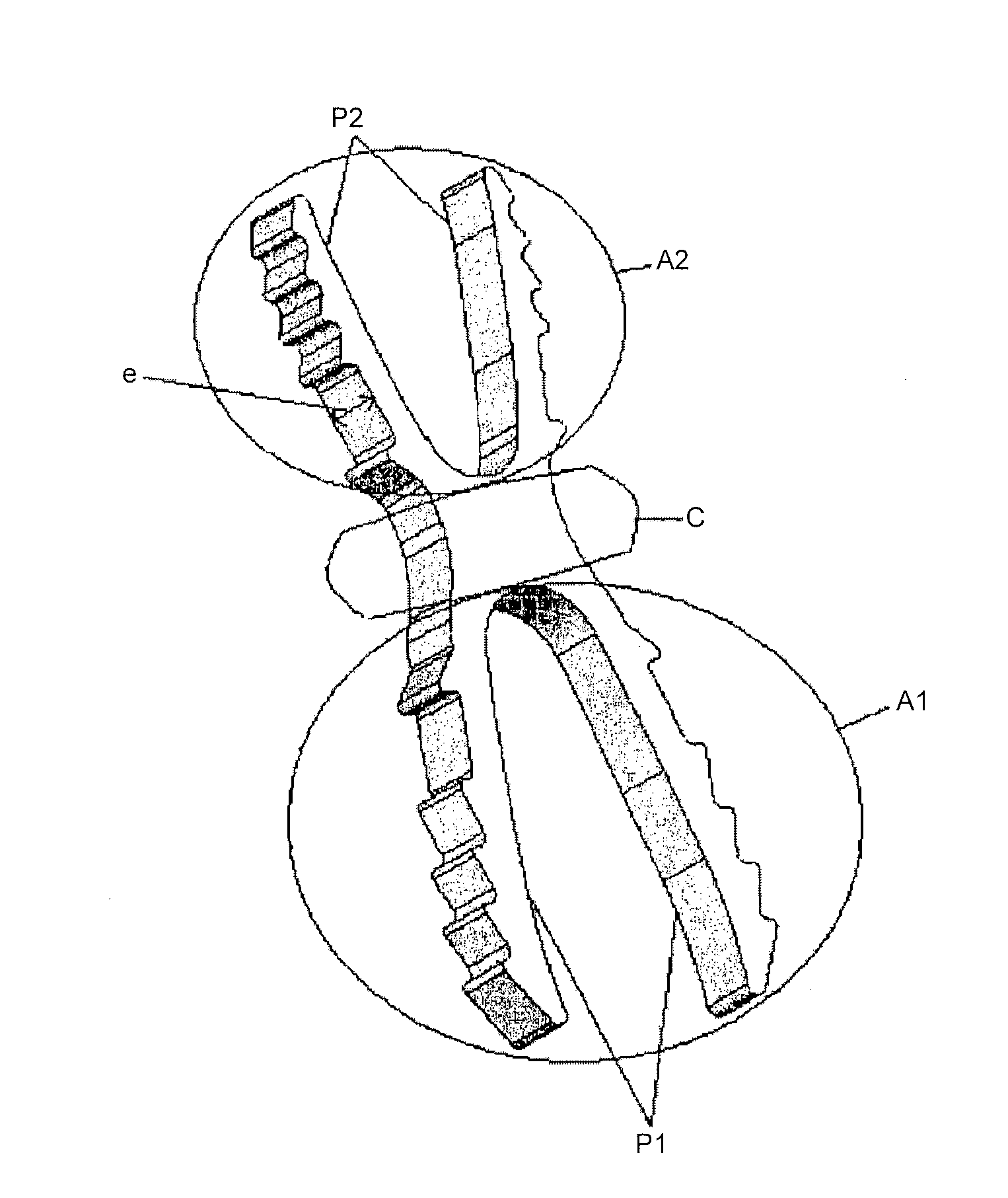
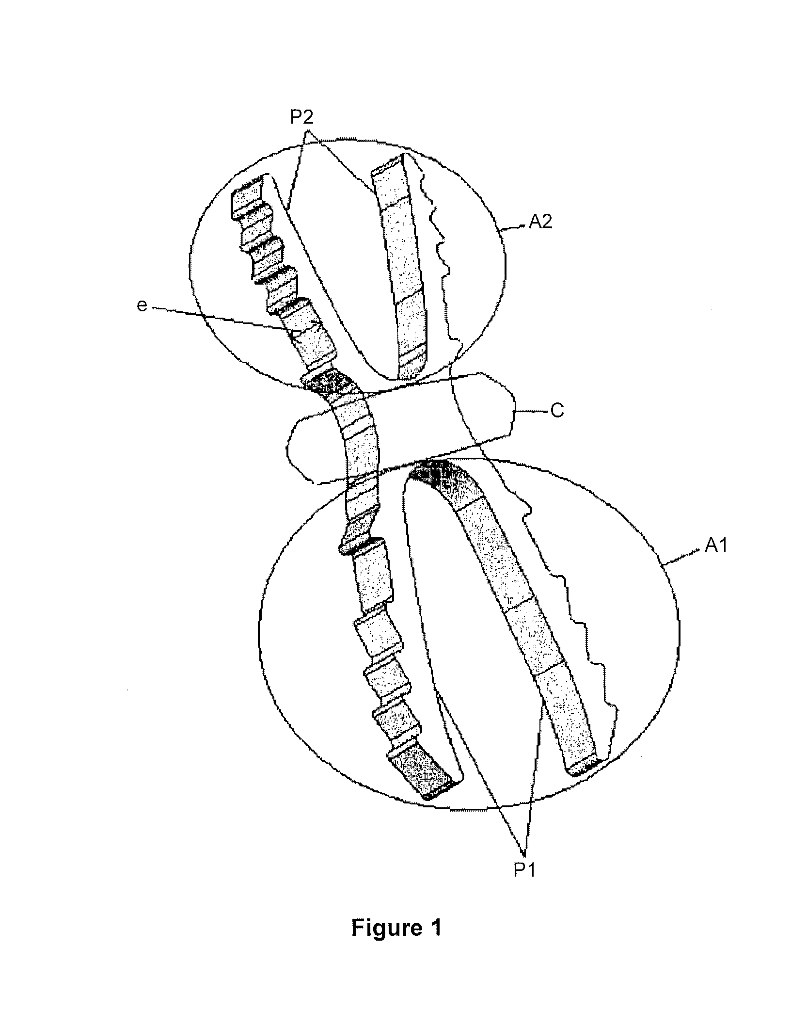
[0075]In a particular embodiment, intended for a distal interphalangeal arthrodesis (hand), the implant is prepared from a superelastic Nitinol alloy (nickel titanium in the weight proportion 55.8% nickel and 44.2% titanium).

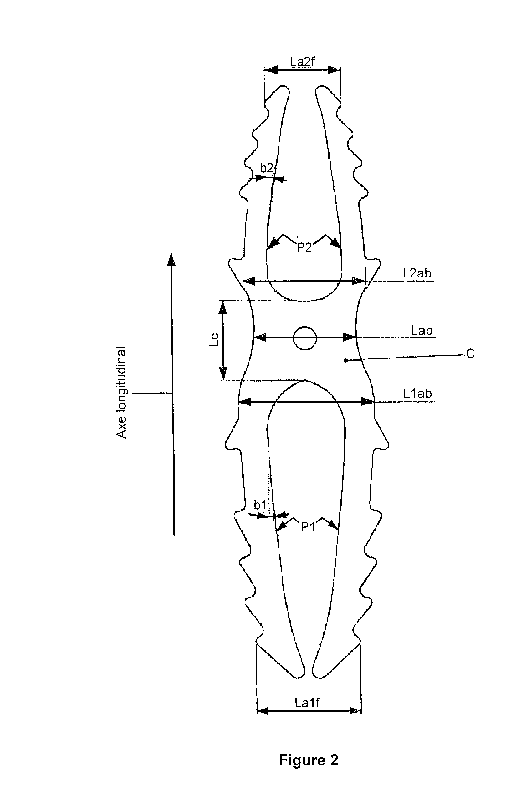
[0076]The cross section of the central zone C is Lab×e=2.8×1.2 mm and the legs are asymmetrical to adapt better to the shapes of the bone, minimize the implanted metal section and allow sufficient expansion for good anchorage. The length of the legs is L2=6.5 mm distal side P2 and L1=9 mm proximal side P1. The length of the central zone C is 3 mm, allowing a slight offset during closure, without affecting the shear strength. To adapt to the surgeon's choice, this central zone may be bent (typically flat or 15O or 25O).

[0077]In the closed position, the width of the proximal base L1ab is 3.8 mm and of the distal base L2ab is 3.0 mm. The opening of the legs P1 and P2 is 2.5 mm or 2.2 mm, that is La1 is 6.3 mm and La2 is 5.2 mm. In the open position the angle at the...


PUM


Abstract

A method for fusing a joint, which includes the step of inserting a first anchoring zone of an arthrodesis device being in a first closed position into a first opening within a first bone. The first anchoring zone includes a first pair of legs. Each leg is capable of transitioning between the first closed position and a first open position for internally gripping the first opening. Also, included in the method is the step of inserting a second anchoring zone of the arthrodesis device being in a second closed position into a second opening within a second bone. The second anchoring zone includes a second pair of legs. Each leg is capable of transitioning between the second closed position and a second open position for internally gripping the second opening.

Description

CROSS-REFERENCE TO RELATED APPLICATIONS[0001]This application is a continuation of U.S. application Ser. No. 13 / 686,074, filed Nov. 27, 2012, which is a continuation of U.S. application Ser. No. 12 / 531,577, filed Feb. 1, 2010, now U.S. Pat. No. 8,394,097, which is a national phase entry under 35 U.S.C. §371 of International Application No. PCT / FR2008 / 050453 filed Mar. 14, 2008, published in French, which claims priority from FR 0702003 filed Mar. 20, 2007, all of which are hereby incorporated herein by reference.FIELD OF THE INVENTION[0002]The invention relates to the technical field of orthopaedic implants, in particular for arthrodeses and osteosyntheses.BACKGROUND OF THE INVENTION[0003]It may be recalled that an osteosynthesis implant must serve to hold in place two (or more) parts of the same bone fractured or cut by a surgical operation (osteotomy), for the time necessary for the consolidation of this bone (typically 3 months).[0004]It may be recalled that an arthrodesis is the...

Claims


Application Information

Patent Timeline
17 Oct 2013
Publication
US20130274746A1
IPC
A61B17/72
CPC
A61B17/72; A61B17/7225; A61B17/7266; A61B17/7283; A61B17/7291; A61F2/4241; A61F2002/30092; A61F2002/30166
Inventors
PEYROT, JACQUES; MEUSNIER, TRISTAN