Air conditioner

a technology for air conditioners and air filters, which is applied in the field of air conditioners, can solve the problems of unstable flow of blown out air, deterioration of air flow characteristics, and inability to stabilize the amount of air blown out from the blowout port, so as to reduce the risk of air blowing, stabilize the flow, and reduce the effect of static pressur

Active Publication Date: 2013-10-24
SHARP KK
View PDF2 Cites 8 Cited by
  • Summary
  • Abstract
  • Description
  • Claims
  • Application Information

AI Technical Summary

Benefits of technology

[0015]As described above, in the air conditioner according to the present invention, the restricting section is arranged at the corner section of the side wall of the air passage and is formed to have the shape by which the air passage sectional area is gradually changed.
[0016]Therefore, in the area near the side wall in which area the air flow tends to become unstable, the air flow can be stabilized, and the static pressure can be increased while the air-blowing resistance is minimized.

Problems solved by technology

For this reason, there is a problem that, when a large amount of dust and dirt adhere to the air filter arranged at the suction port in actual use, that is, during high dust load, the amount of air blown out from the blowout port is not stabilized, and thereby the air flow characteristics are deteriorated.
Further, the air conditioner provided with the cross flow fan has a characteristic that, when a load is applied to the cross flow fan, in the vicinity of the side wall of each of the left and right ends of the blowout port, the flow of blown out air tends to become unstable due to the influence of the resistance of the side wall, and to generate abnormal “flapping” sound which also becomes the cause of the noise.

Method used


Image

  • Air conditioner
  • Air conditioner
  • Air conditioner

Examples


Embodiment Construction

[0025]In the following, an embodiment according to the present invention will be described with reference to the accompanying drawings. In the present embodiment, an indoor unit of a separate type air conditioner will be described as an example. In the air conditioner of this type, a heat exchanger housed in an indoor unit, and a compressor, a four way valve, an outdoor heat exchanger, and a restriction device (all not shown), which are housed in an outdoor unit (not shown), are connected by a refrigerant pipe to form a refrigerating cycle, and thereby various modes of operation, such as cooling, heating, and dehumidification operations, can be performed.

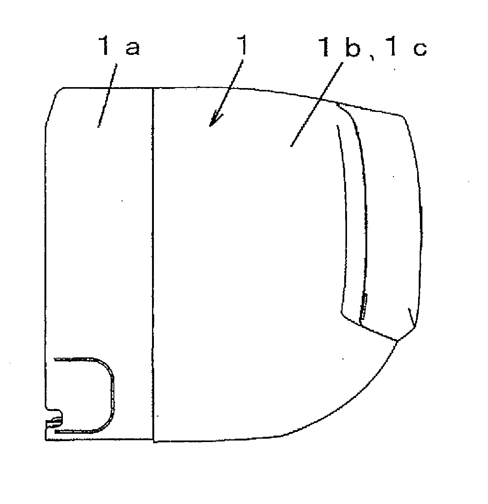
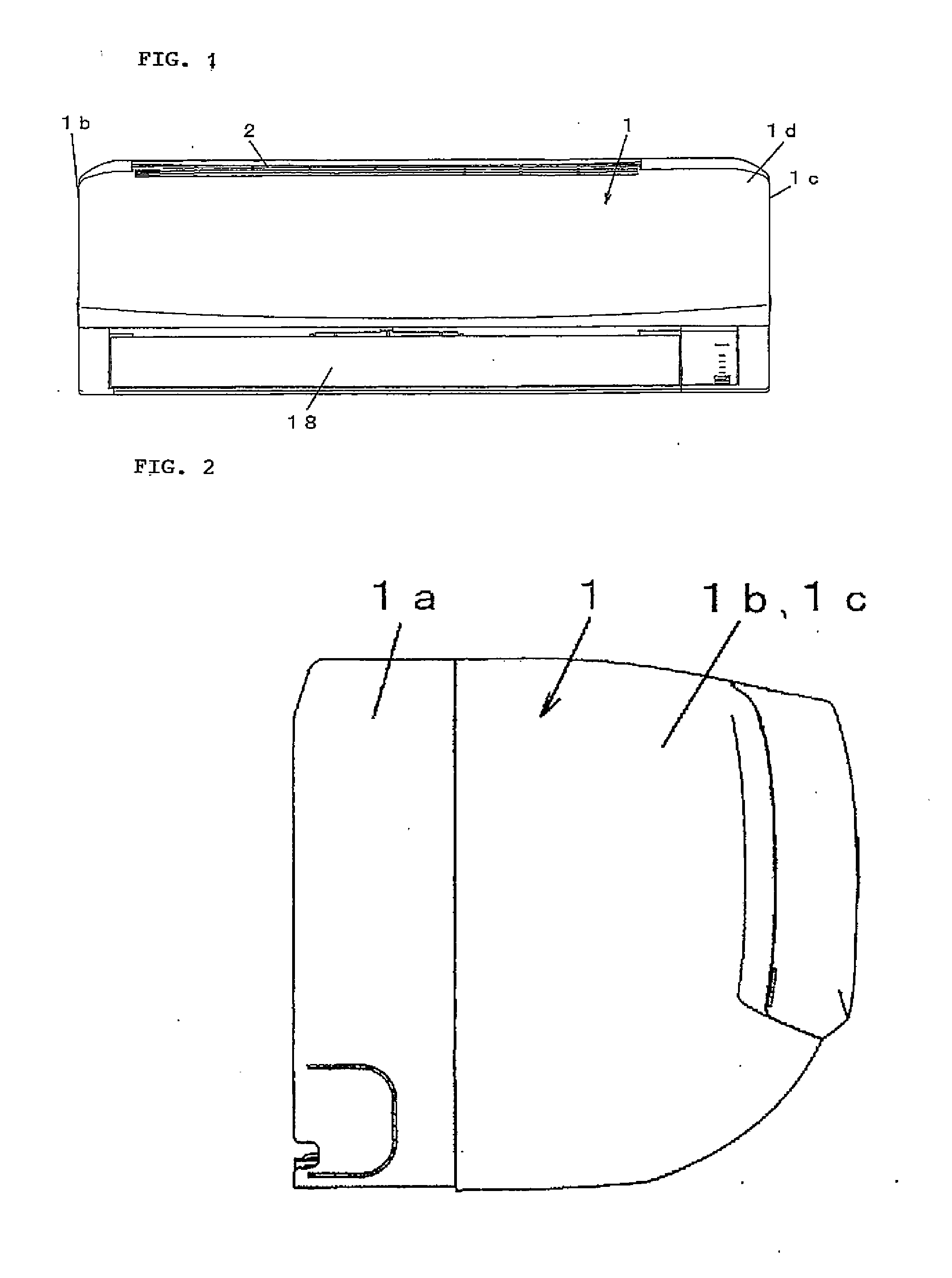
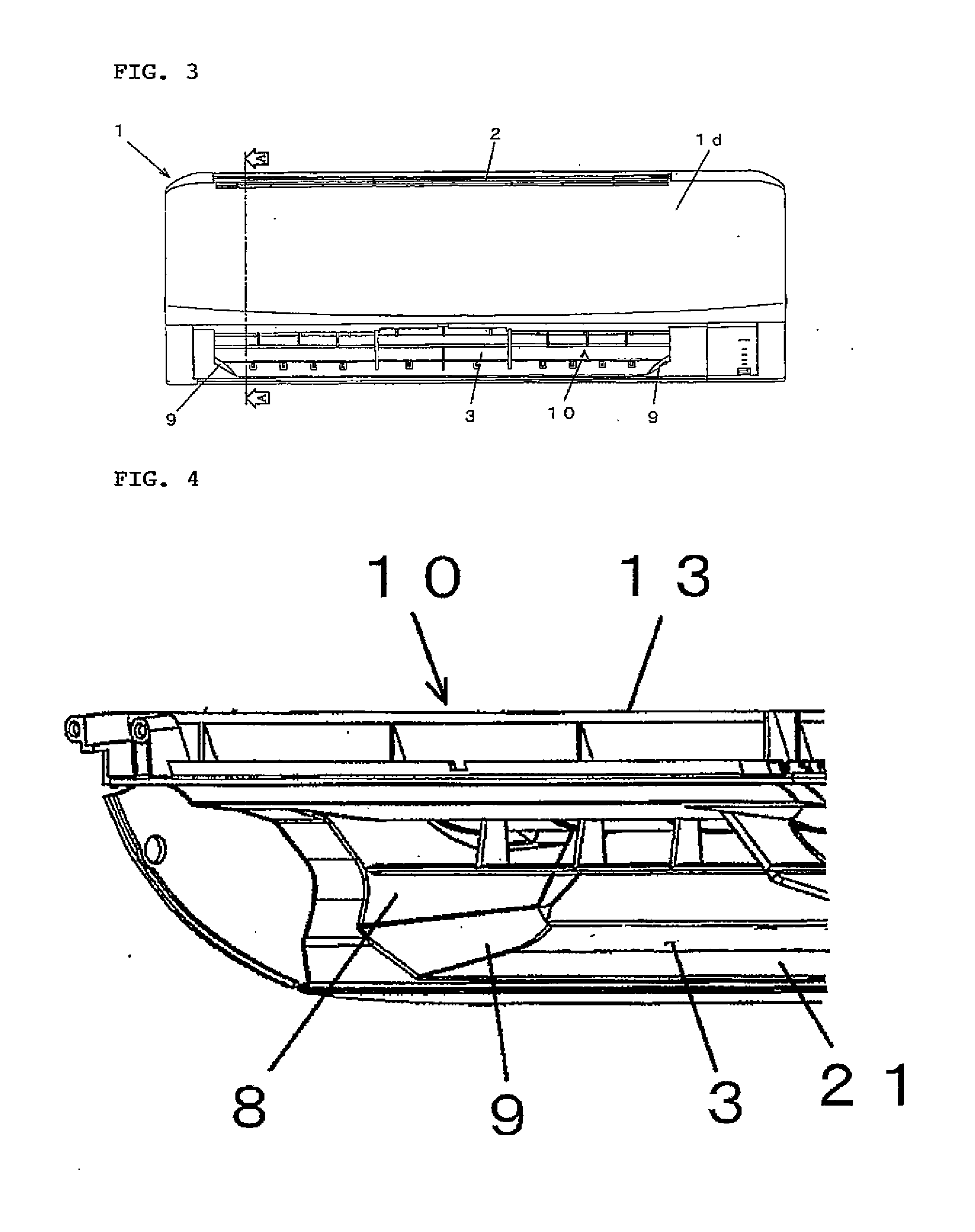
[0026]As shown in FIG. 5, the indoor unit includes, in a housing 1, an air passage 4 extending from a suction port 2 to a blowout port 3, a heat exchanger 5 arranged on an upstream side of the air passage 4, a cross flow fan 6 arranged in the air passage 4 on a downstream side of the heat exchanger 5, and a tubular air passage wall ...


PUM


Abstract

The present invention is to provide an air conditioner provided with a cross flow fan having sufficient air blowing efficiency. The air conditioner includes, in a housing, an air passage extending from a suction port to a blowout port, a heat exchanger arranged at the upstream side of the air passage, a cross flow fan arranged in the air passage on the downstream side of the heat exchanger, and an air passage wall provided in a downstream area of the cross flow fan to reach the blowout port. A restricting section, which restricts an air passage sectional area, is provided at a corner section of the side wall of the air passage wall, which side wall is located at each of both shaft direction ends of the cross flow fan. The restricting section is formed to have a shape by which, in a downstream area of the cross flow fan, the air passage sectional area having a rectangular cross section expanding from the upstream side to the downstream side is restricted so as to reduce an enlargement ratio of the air passage sectional area. Further, the restricting section has a smooth restricting surface crossing the corner section of the cross section of the air passage, and the cross-sectional shape of the restricting surface is set to be gradually enlarged from the upstream side to the downstream side of the air flow.

Description

TECHNICAL FIELD[0001]The present invention relates to an air conditioner provided with a cross flow fan.BACKGROUND ART[0002]In a recent energy saving trend, there has been an increasing demand for improving the performance of an air blower of an air conditioner. The performance of an air blower is enhanced by improving the flow characteristic of the air passage in which the air blower is arranged, and by reducing the noise level.[0003]In order to respond to the demand, in the conventional air conditioner, the performance of the air blower is improved by expanding the suction port of the air passage and by increasing the minimum distance between the stabilizer and the rear guider which are respectively arranged on the front and rear sides of the cross flow fan configuring the air blower.[0004]However, with such means, the performance of the air blower can be improved, but the air blower becomes a low static pressure type. For this reason, there is a problem that, when a large amount ...

Claims


Application Information

Patent Timeline
Patent Type & Authority Applications(United States)
IPC IPC(8): F25D17/08
CPCF25D17/08F24F13/24F24F1/0011F24F1/0057
Inventor TAKAHASHI, MASAYAOHTSUKA, MASAKISHIRAICHI, YUKISHIGE
Owner SHARP KK
Why Eureka
Try Eureka