Gas generator

Inactive Publication Date: 2013-10-24
NIPPON KAYAKU CO LTD +1
View PDF8 Cites 14 Cited by
  • Summary
  • Abstract
  • Description
  • Claims
  • Application Information

AI Technical Summary

Benefits of technology

[0026]According to the present invention, a gas generator which can achieve reduced cost, have le

Problems solved by technology

In contrast, since a shape of a portion of the lower shell to which the igniter is to be assembled has been complicated, the lower shell has generally been fabricated by cutting that portion (a portion of the low

Method used


Image

  • Gas generator
  • Gas generator
  • Gas generator

Examples


embodiment 1

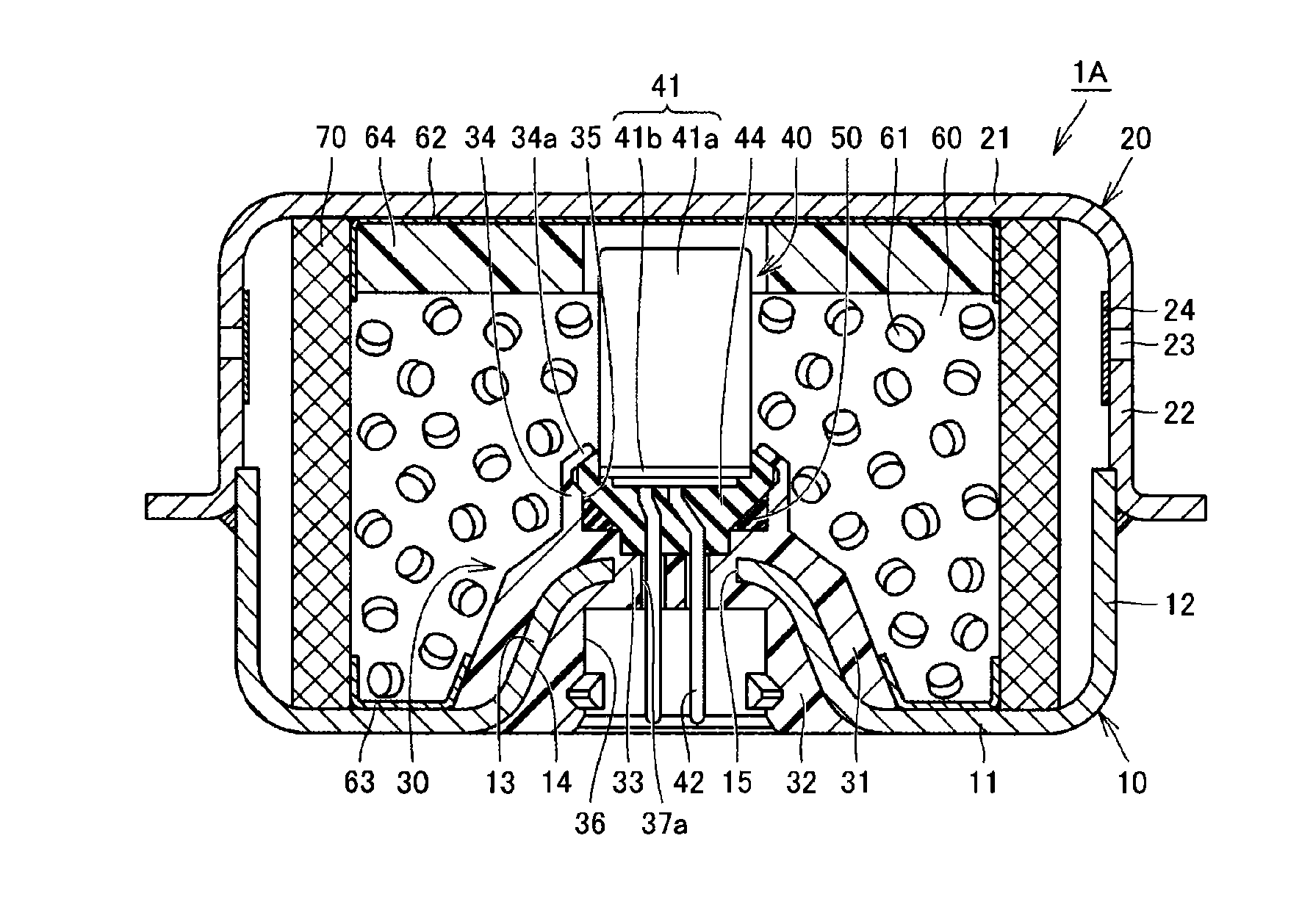
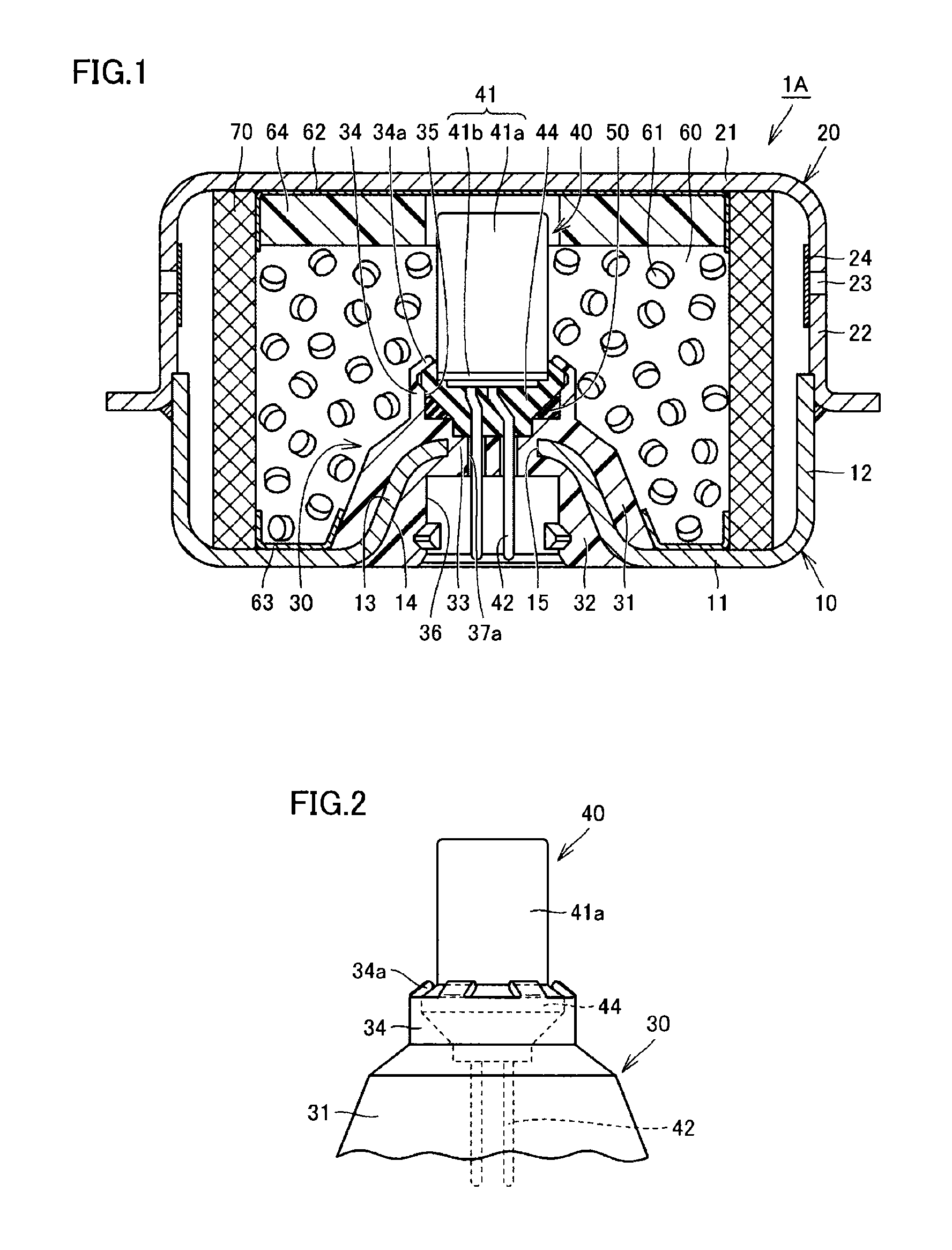
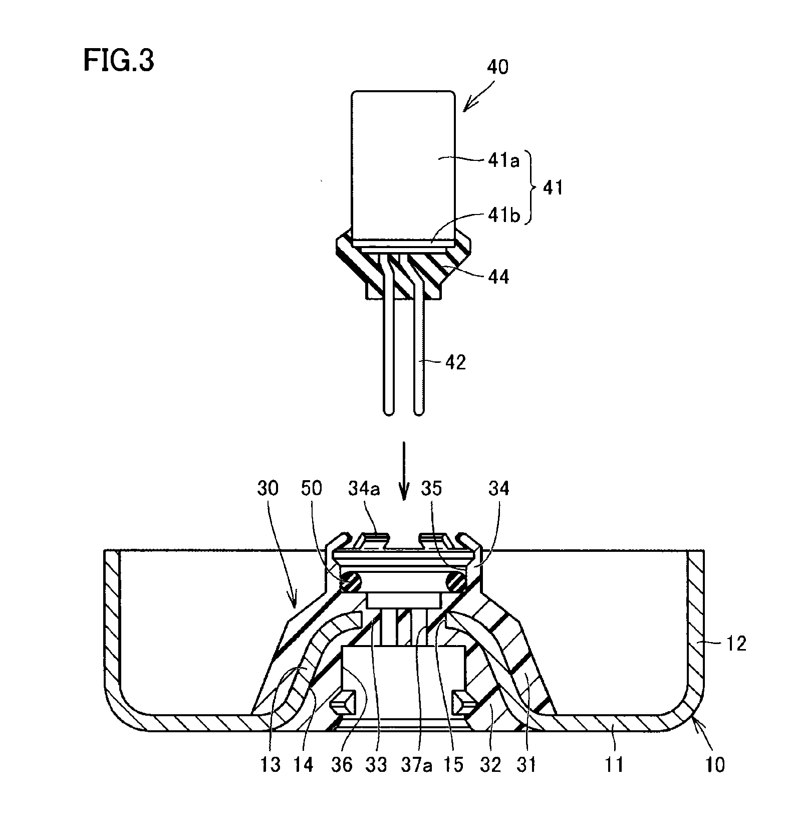
[0059]FIG. 1 is a schematic diagram of a gas generator in Embodiment 1 of the present invention. An overall structure of a gas generator 1A in the present embodiment will initially be described with reference to this FIG. 1.

[0060]As shown in FIG. 1, gas generator 1A in the present embodiment has a short cylindrical housing having opposing axial ends closed, and is constructed to accommodate as components in this housing, a holding portion 30, an igniter 40, a gas generating agent 61, a filter 70, and the like. The short cylindrical housing includes a lower shell 10 and an upper shell 20. Each of lower shell 10 and upper shell 20 is made of a press-formed product formed by press-working one plate-shaped member made of metal.

[0061]Lower shell 10 and upper shell 20 are each formed in a cylindrical shape with bottom, and an outer shell portion of the housing is formed by combining and joining the shells such that open surfaces thereof face each other. Lower shell 10 has a bottom plate p...

embodiment 2

[0113]FIG. 7 is a schematic diagram of a gas generator in Embodiment 2 of the present invention. In addition, FIG. 8A is a plan view of the holding portion of the gas generator in the present embodiment, and FIG. 8B is a bottom view of the igniter. A construction of a gas generator 1B in the present embodiment will be described below with reference to these FIGS. 7, 8A, and 8B.

[0114]As shown in FIG. 7, gas generator 1B in the present embodiment is different from gas generator 1A in Embodiment 1 of the present invention described above in a shape of coupling portion 33 of holding portion 30. Specifically, in gas generator 1B in the present embodiment, an insertion hole 38 provided in coupling portion 33 is not in a shape corresponding to a shape of a pair of terminal pins 42 of igniter 40 but it is formed from a single hole in a larger perfect circle shape when viewed two-dimensionally. Therefore, insertion hole 38 does not have a function as the first rotation prevention mechanism.

[...

embodiment 3

[0120]FIG. 10 is a schematic diagram of a gas generator in Embodiment 3 of the present invention. A construction of a gas generator 1C in the present embodiment will be described below with reference to this FIG. 10.

[0121]As shown in FIG. 10, gas generator 1C in the present embodiment is different from gas generator 1A in Embodiment 1 of the present invention described above in a surface shape of protruding cylindrical portion 13 provided in lower shell 10. Specifically, in gas generator 1C in the present embodiment, a plurality of recess portions 16 are provided in a surface of protruding cylindrical portion 13 located on the side of combustion chamber 60.

[0122]The plurality of recess portions 16 are in a shape not continuously going around protruding cylindrical portion 13 at least along the circumferential direction (that is, a shape which is not an annular groove), and they are formed, for example, by being formed simultaneously with press-working of lower shell 10 or by providi...


PUM


Abstract

A gas generator includes a lower shell, an upper shell, a holding portion, an igniter, and a filter. The lower shell is made of a press-formed product formed by press-working one plate-shaped member made of metal, and includes a protruding cylindrical portion and an opening provided in the protruding cylindrical portion. The holding portion is formed from a resin-molded portion formed by attaching an insulating fluid resin material to a bottom plate portion so as to reach a part of an outer surface from a part of an inner surface of the bottom plate portion of the lower shell through the opening and solidifying the same, and includes an accommodation recess portion in a portion opposed to a top plate portion. The igniter is held by the holding portion while it is inserted in the accommodation recess portion from a side of the top plate portion and fitted therein.

Description

TECHNICAL FIELD[0001]The present invention relates to a gas generator incorporated in a passenger protection apparatus, and more particularly to what is called a disc type gas generator incorporated in an air bag apparatus equipped in a steering wheel or the like of a car.BACKGROUND ART[0002]From a point of view of protection of a driver and / or a passenger in a car or the like, an air bag apparatus which is a passenger protection apparatus has conventionally widely been used. The air bag apparatus is equipped for the purpose of protecting a driver and / or a passenger against shock caused at the time of collision of a vehicle or the like, and it receives a body of a driver or a passenger with an air bag serving as a cushion, as the air bag is expanded and developed instantaneously at the time of collision of the vehicle or the like. The gas generator is equipment which is incorporated in this air bag apparatus, an igniter therein being ignited in response to power feed through a contr...

Claims


Application Information

Patent Timeline
IPC IPC(8): C06D5/00
CPCC06D5/00B60R21/2644B60R2021/26029B60R2021/26076
Inventor OHSUGI, SATOSHITANAKA, YUSUKEMUKUNOKI, HIROTAKAKIM, JIN HAN
Owner NIPPON KAYAKU CO LTD
Why Eureka
Try Eureka