Floating support for an offshore structure, in particular such as a wind turbine

a technology for offshore structures and support beams, which is applied in the direction of special-purpose vessels, vessel construction, transportation and packaging, etc., can solve the problems of difficult handling and installation, and relatively expensive manufacturing

Active Publication Date: 2013-10-24
DCNS SA
View PDF1 Cites 25 Cited by
  • Summary
  • Abstract
  • Description
  • Claims
  • Application Information

AI Technical Summary

Problems solved by technology

However, one can see that such means in the form of a float use a significant quantity of steel, are relatively difficult

Method used


Image

  • Floating support for an offshore structure, in particular such as a wind turbine
  • Floating support for an offshore structure, in particular such as a wind turbine
  • Floating support for an offshore structure, in particular such as a wind turbine

Examples


Embodiment Construction

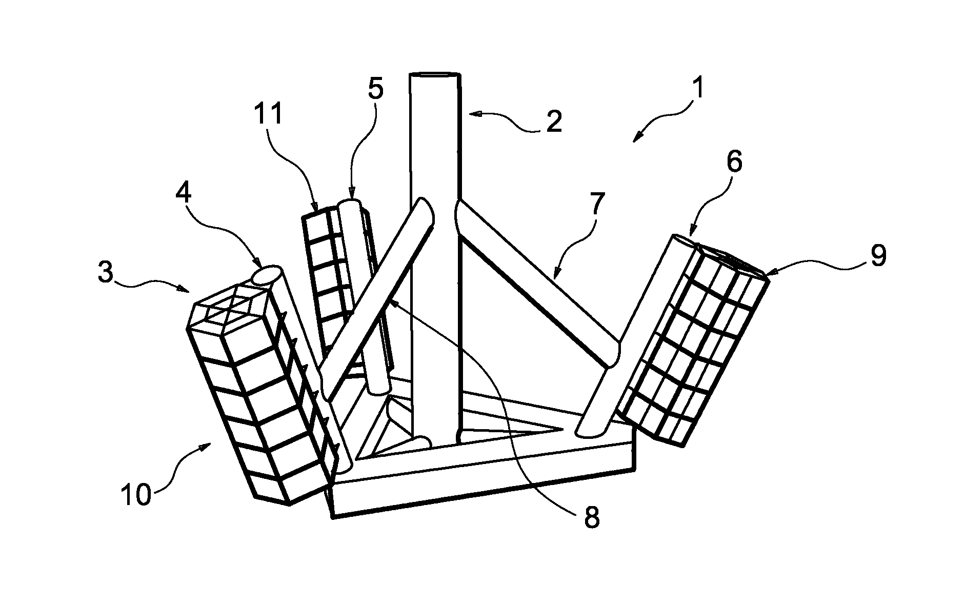
[0019]The figures, and in particular FIG. 1, show a floating support for an offshore structure, in particular such as a wind turbine.

[0020]The support is designated by general reference 1 in this FIG. 1 and traditionally includes means in the form of a support mast designated by general reference 2, the upper part of which is associated with the structure, for example such as the nacelle of the wind turbine, and the lower part of which is associated with means in the form of a float designated by general reference 3 in that figure.

[0021]In general, these float-forming means include a structure with a base of support columns and beams, for example made from metal and welded to each other.

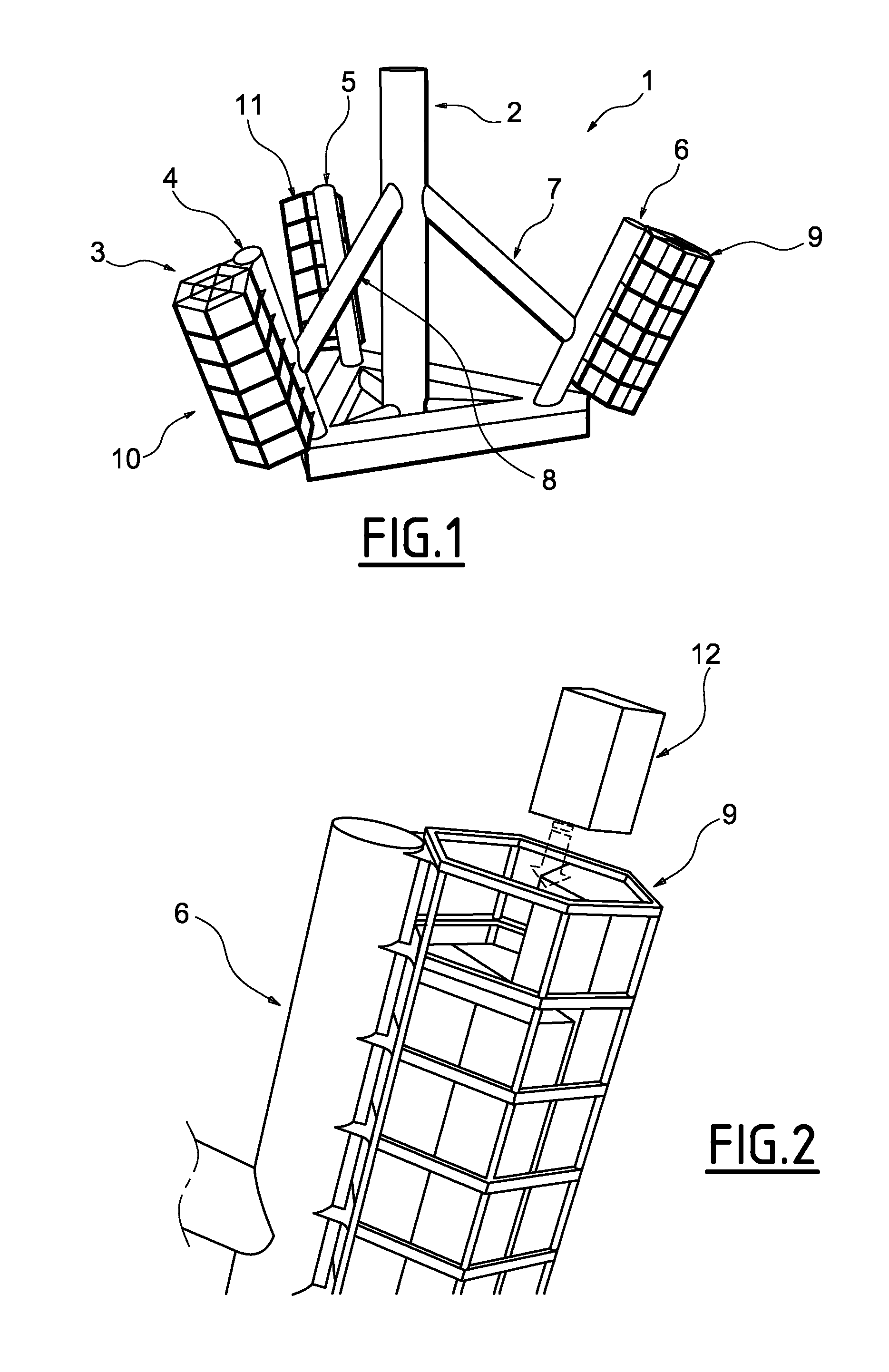
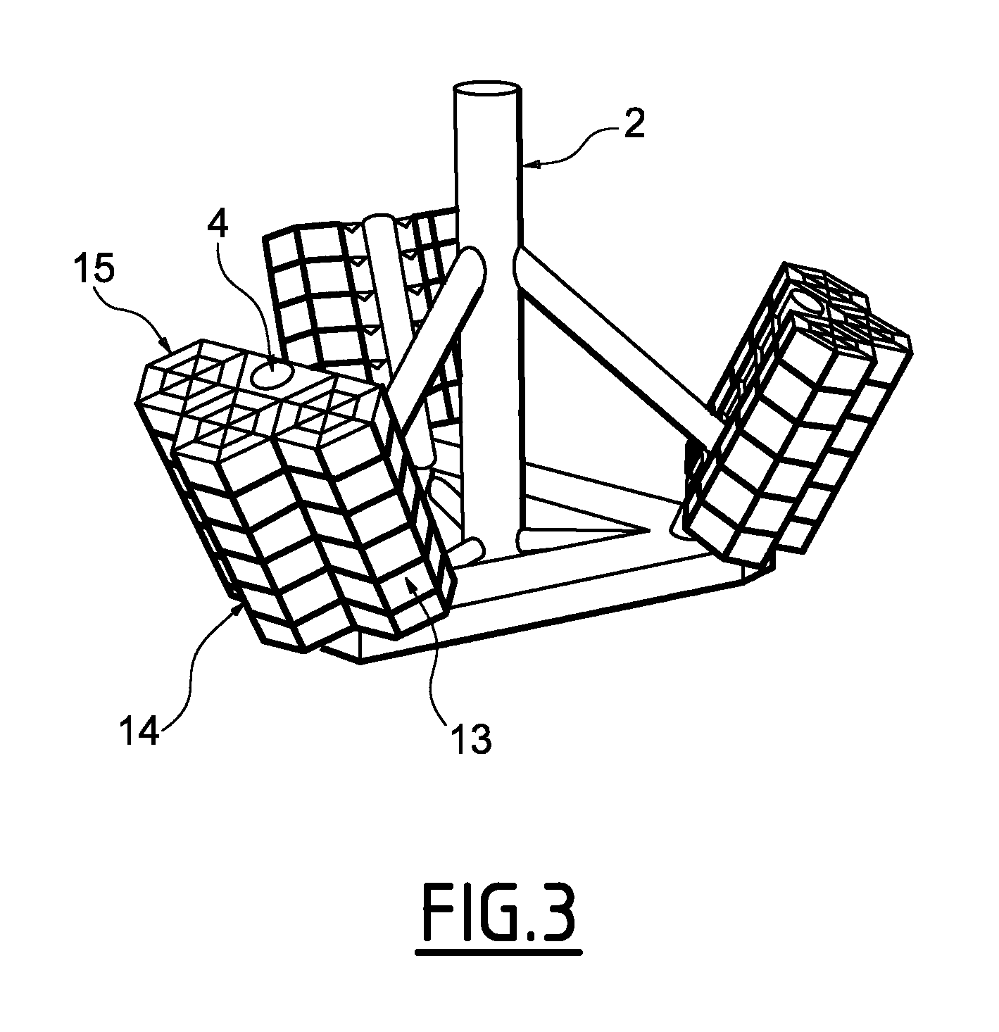
[0022]Three columns are for example designated by general references 4, 5, and 6 in these figures, and are distributed around means in the form of a support mast while two beams 7 and 8, respectively, are also illustrated.

[0023]In fact and in the illustrated example, these means form a base that has ...


PUM

PropertyMeasurementUnit
Shapeaaaaaaaaaa
Buoyancyaaaaaaaaaa

Abstract

This floating support (1) for an offshore structure, in particular such as a wind turbine, of the type including means in the form of a support mast (2), the upper part of which is associated with the structure and the lower part of which is associated with means in the form a float (3), is characterized in that the means in the form a float (3) comprise means in the form of a cage (9, 10, 11) for receiving buoyancy tanks (12).

Description

FIELD OF THE INVENTION[0001]The present invention relates to a floating support for an offshore structure, in particular such as a wind turbine. More particularly, the invention relates to such a floating support that includes means in the form of a support mast, the upper part of which is associated with the structure, for example such as a nacelle of the wind turbine, and the lower part of which is associated with means in the form of a float, and possibly means forming a ballast.BACKGROUND OF THE INVENTION[0002]A wide variety of floating supports of this type are already known in the state of the art.[0003]As a general rule, the float-forming means are made by welding and assembling large metal tubes making it possible to obtain the desired level of buoyancy.[0004]However, one can see that such means in the form of a float use a significant quantity of steel, are relatively difficult to handle and install, and are relatively expensive to manufacture due to the material and the ma...

Claims


Application Information

Patent Timeline
IPC IPC(8): B63B35/44
CPCB63B35/44Y02E10/727B63B1/107B63B1/125B63B3/06B63B5/24B63B2001/128B63B2005/245B63B2035/446B63B35/4406
Inventor THIEFFRY, PHILIPPEMOIRET, CYRILLE JACQUES
Owner DCNS SA
Why Eureka
Try Eureka