Applicator device for applying a cosmetic, applicator element therefor, and cosmetic unit comprising the applicator device

a technology of applicator device and cosmetic, which is applied in the direction of applications, packaging goods, brushes, etc., can solve the problem that the arrangement of the application organ/bristle attached with the flocking method cannot always be predicted accurately, and achieve the effect of convenient assembly

Inactive Publication Date: 2013-10-24
GEKA
View PDF5 Cites 20 Cited by
  • Summary
  • Abstract
  • Description
  • Claims
  • Application Information

AI Technical Summary

Benefits of technology

[0028]Furthermore, it is an advantage of the invention that it can be readily assembled by arranging several, even different, applicator elements in almost any way. In this case, the applicator elements may differ with regard to a length h of the application organs, the hardness, the geometry of the application organs or the covering with application organs, or with regard to the design. Combining an applicator element manufactured by a single-component injection-molding process with another applicator element, which, for example, has been manufactured by a two--component injection-molding process or, for example, by 3-D printing, also lies within the scope of the invention.
[0029]It is another object of the invention to provide suitable applicator elements for forming an applicator device according to the invention.
[0030]An applicator element according to the invention comprises a plurality of application organs and is suitably configured for the axially successive arrangement along a longitudinal axis of an applicator device, with at least a part of the application organs being disposed and / or configured for this purpose in such a way that free ends of the application organs protrude in the axial direction over an axial length 1 of a base part at least to some extent, or end flush with it. Thus, application organs are provided which protrude over a base part at least on one end or that end flush with it, and which, when assembled with other applicator elements that also comprise bristles / application organs that protrude or end flush, can together form an overlap zone Ü within the sense of the invention.
[0031]In this case, the application organs preferably form a bristle area BF / enveloping volume U, which has a longitudinal extent l′ with respect to the longitudinal axis L of the applicator element, the longitudinal extent l′ being at least equal to, particularly greater than, the longitudinal extent l of the base part of the applicator element.
[0032]A difference l′-l resulting therefrom forms the projecting length with respect to the longitudinal extent of the base part, the projecting length preferably being disposed symmetrically to the base part in the axial direction. This means that the ends of the application organs protrude to the same extent over the base part of the applicator element on both ends. Nevertheless, an enveloping volume U formed by the bristle area Bf can be disposed non-symmetrically with respect to the longitudinal extent of the base part, so that, for example, the bristle area does not protrude over, in particular end flush with, the base part on one end, and the entire difference projecting length l-l′ is disposed so as to protrude on one end over the end face of the base part.
[0033]In this case, the enveloping volume can also be disposed eccentrically with respect to the longitudinal axis L of the applicator element.

Problems solved by technology

Such an applicator is disadvantageous in that the arrangement of the application organs / bristles attached with the flocking method cannot always be predicted accurately and is subject to chance to a certain extent.
Thus, the formation of overlapping bristle regions, particularly the shape and extent in space of the overlapping portions thus formed, depend on chance to a certain degree because it cannot always be ensured that bristles can be disposed at the same density at every location of the carrier part.

Method used


Image

  • Applicator device for applying a cosmetic, applicator element therefor, and cosmetic unit comprising the applicator device
  • Applicator device for applying a cosmetic, applicator element therefor, and cosmetic unit comprising the applicator device
  • Applicator device for applying a cosmetic, applicator element therefor, and cosmetic unit comprising the applicator device

Examples


first embodiment

[0063]Hereinafter, the structure of an applicator element 6a, 6b according to the invention will be described with reference to the illustration according to FIG. 3.

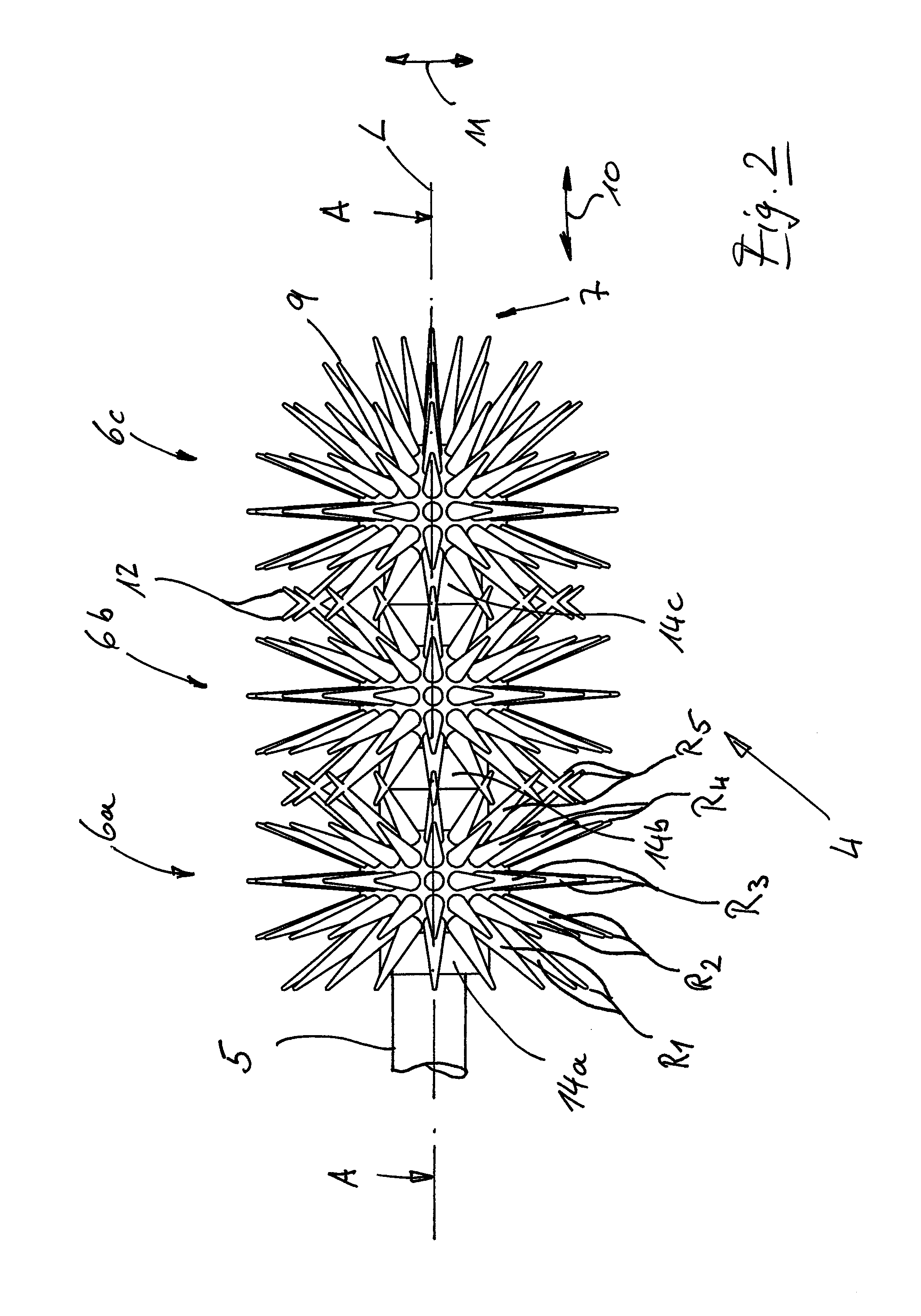
[0064]These applicator elements 6a, 6b comprise the base part 14a, 14b. The base part 14a, 14b has an axial longitudinal extent l and is configured, for example, as a tubular-cylindrical body with a through opening 15. An annular groove 15a provided for axially fixing the applicator elements 6a, 6b on the carrier part 5—as is described further below—is disposed in the through opening 15. In a region that is preferably central with respect to the longitudinal extent l, the base part 14a, 14b comprises a bead-like thickened portion 16. The thickened portion 16 is, for example, a ball-like thickened portion 16 with an outer surface 17, from which the bristles 9 protrude approximately perpendicularly with their central axes 9′.

[0065]All the free ends 12 of the bristles 9 of an applicator element 6a, 6b span an imaginary enve...

second embodiment

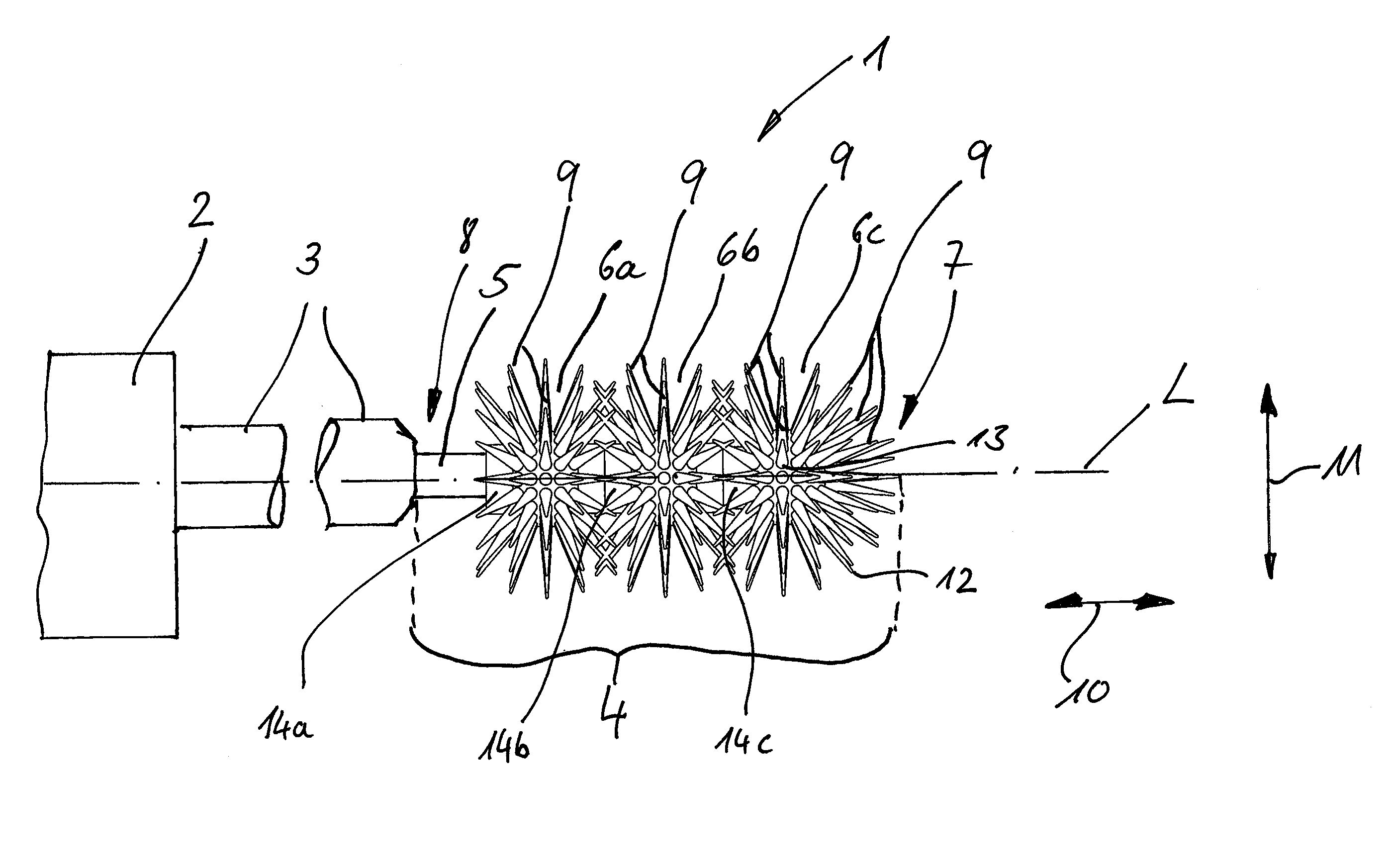
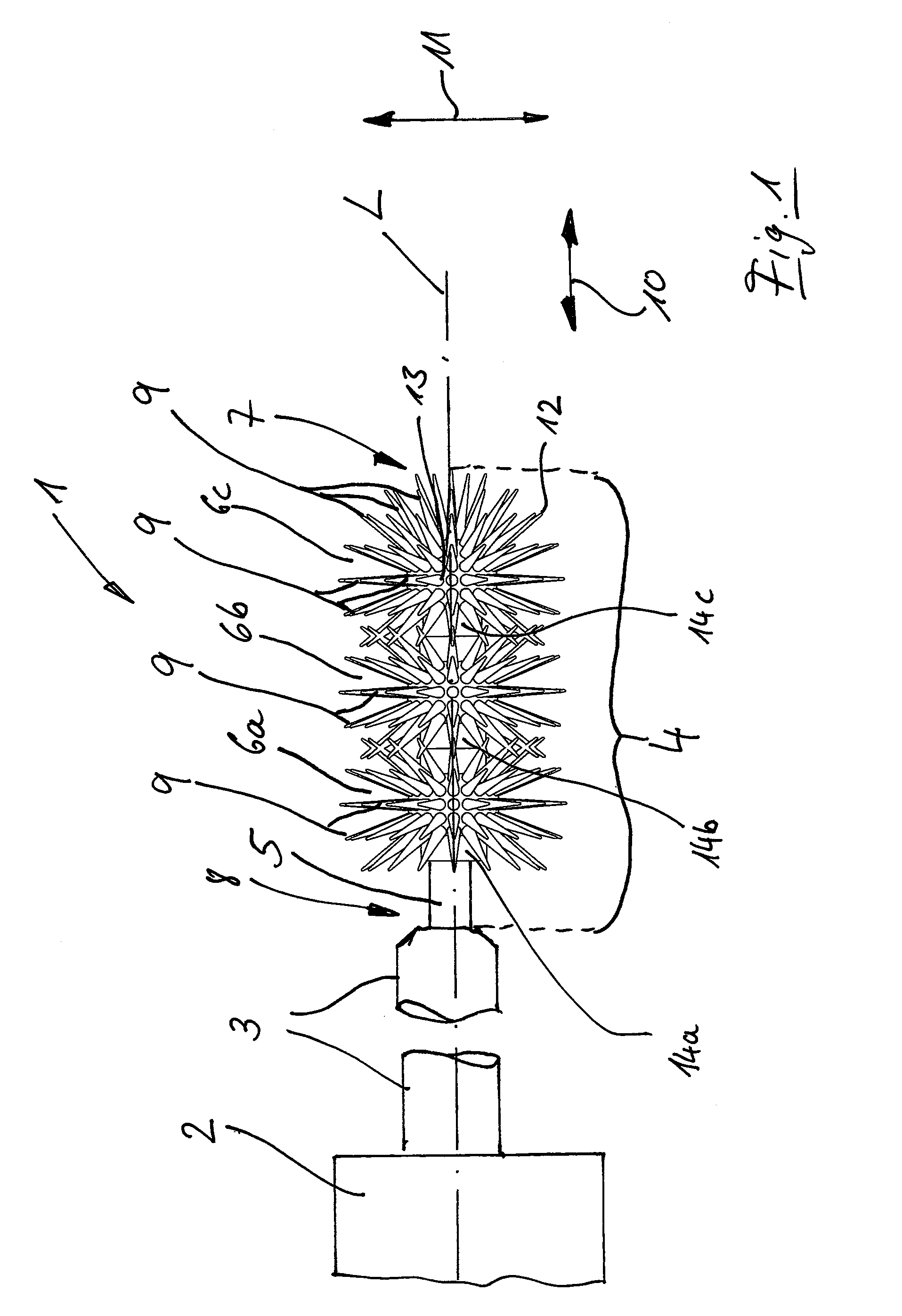
[0077]FIG. 5 shows an applicator element 6c according to the invention, which is particularly suitable as an applicator element 6c in the region of the distal end 7 of the applicator device 4. Towards the proximal end 8 of the applicator device 4, the applicator element 6c is configured exactly like the applicator elements 6a, 6b with regard to the configuration of the base part 14c and with regard to the bristle covering BF. In contrast to these applicator elements 6a, 6b, the applicator element 6c comprises in the area of the distal end 7 another bristle covering, so that the distal end 7 of the applicator device 4 itself can also be used as an end-face applicator, because a dense bristle covering is provided at the end face.

[0078]In further contrast to the applicator elements 6a, 6b, the applicator element 6c comprises a tapped recess 15b, which also comprises an annular groove 15a, instead of the through opening 15. With the tapped recess 15b, the applicator element 6c—as is des...


PUM


Abstract

The invention relates to an applicator device for a cosmetic applicator, in particular a mascara applicator, comprising at least two applicator elements having application units, wherein the applicator elements are designed as one-piece plastic parts and one or more applicator elements are arranged axially consecutively along a longitudinal axis L of the applicator device, wherein the application units of the applicator elements form application unit fields, each spanning an enveloping volume, wherein at least two enveloping volumes of applicator elements arranged next to one another are in contact with each other forming an overlapping zone, or overlap each other at least partially. The invention further relates to an applicator element for forming an applicator device, to a cosmetic applicator, and to an applicator element of an applicator device.

Description

FIELD OF THE INVENTION[0001]The invention relates to an applicator device comprising at least 2 applicator elements, an applicator element, a cosmetics applicator and a cosmetics unit.BACKGROUND OF THE INVENTION[0002]A cosmetics application brush wherein bristles are deposited on a bristle core by means of a flocking method is known from DE 32 31 574 A1. The core comprises ring-like projections, so that the bristles deposited in the flocking method overlap in partial areas, particularly in the transition region from the annular projections to the core of the carrier part.[0003]Such an applicator is disadvantageous in that the arrangement of the application organs / bristles attached with the flocking method cannot always be predicted accurately and is subject to chance to a certain extent. Thus, the formation of overlapping bristle regions, particularly the shape and extent in space of the overlapping portions thus formed, depend on chance to a certain degree because it cannot always...

Claims


Application Information

Patent Timeline
Patent Type & Authority Applications(United States)
IPC IPC(8): A45D40/26
CPCA45D40/262A46B3/005A46B7/042A46B7/10A46B9/021A46B9/025A46B2200/1053B33Y80/00
Inventor KULIK, DANIELAFISCHER, WERNERTHIERER, GUDRUN
Owner GEKA
Why Eureka
Try Eureka