Directional valve equipped with pressure control

a technology of directional valves and pressure control, which is applied in the direction of valve operating means/releasing devices, mechanical equipment, transportation and packaging, etc., can solve the problems of complex manufacturing and assembly, a lot of separate components,

Active Publication Date: 2013-10-24
PARKER HANNIFIN MFG FINLAND
View PDF5 Cites 8 Cited by
  • Summary
  • Abstract
  • Description
  • Claims
  • Application Information

AI Technical Summary

Benefits of technology

[0012]By means of the presented solution, there is no need to provide the spool of the direct

Problems solved by technology

However, the directional valve constructed according to the prior art and also comprising pressure cont

Method used


Image

  • Directional valve equipped with pressure control
  • Directional valve equipped with pressure control
  • Directional valve equipped with pressure control

Examples


Embodiment Construction

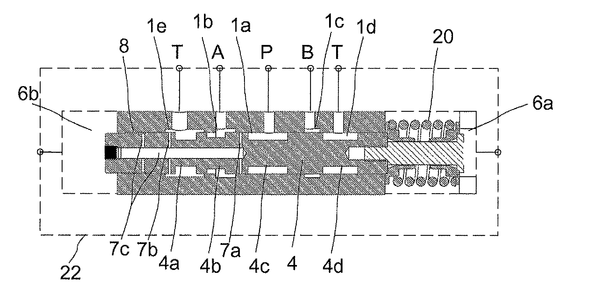
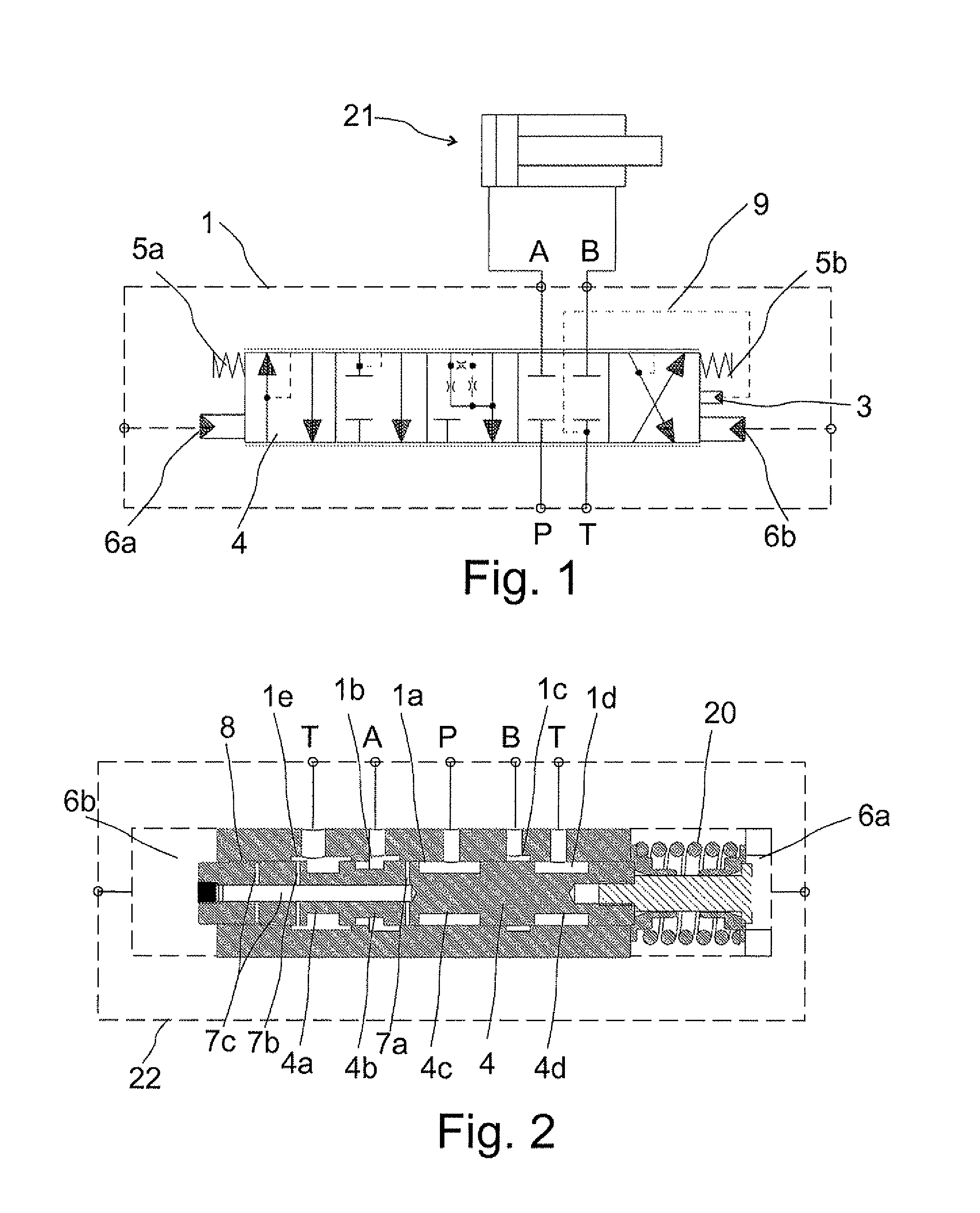
[0020]FIG. 1 shows, by means of graphic symbols of hydraulics and on the principle level, a directional valve in which the pressure control according to the presented solution is applied. In particular, it is a valve suitable for hydraulic oil or various flowing hydraulic fluids.

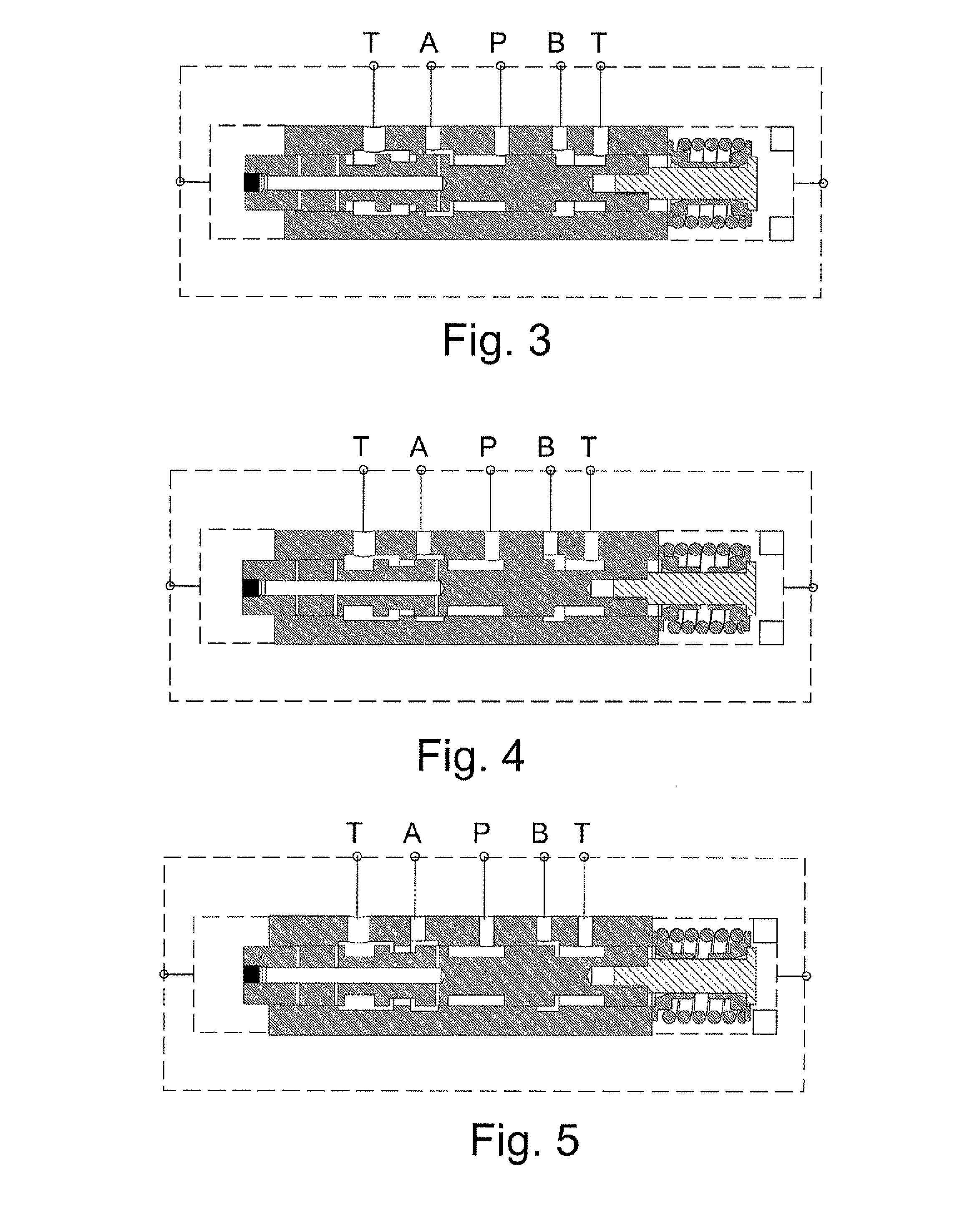
[0021]The valve 1 of FIG. 1 is, in principle, a so-called 4 / 3 directional valve which also comprises two other functional positions for pressure control. The valve 1 comprises a spool 4 which is arranged, in the centre position of the valve 1 (the second coupling position from the right in FIG. 1), to close a pressure port P, a tank port T, and both work ports A and B. When the valve 1 is not under pilot control, the spool 4 is automatically placed in the centre position, for example by means of springs 5a and 5b. The spool 4 is deviated from the centre position by applying forces generated by the pilot control. The spring force generated by the spring is used as a returning force and a counterforce for the ...


PUM


Abstract

A directional valve for controlling an actuator by a pressurized medium, including: a pressure port; a work port; a tank port; a spool moving axially inside the directional valve; a first position of the spool, in which the spool tends to be set, and a second position, to which the spool can be moved by a pilot control force and in which the spool opens the flow of pressurized medium from the pressure port to the work port. The directional valve further includes a feedback chamber in which the pressure generates a feedback force effective on the spool and opposite to the pilot control force. In its second position, the spool guides the pressure of the work port to the feedback chamber, and in the second position, the directional valve generates a feedback force proportional to the pressure of the work port, moving the spool to shut off the flow.

Description

FIELD OF THE INVENTION[0001]The invention relates to a directional valve for controlling an actuator by means of pressurized medium.BACKGROUND OF THE INVENTION[0002]In pressurized medium systems, actuators which perform rotary or linear motions, such as motors and cylinders, are utilized in a known manner. In controlling the actuators, valves are utilized for controlling the pressurized medium for example to control the direction of movement of the actuator or to keep it stationary. Different functions of the actuators are implemented by suitable couplings of different valves.[0003]Several different couplings for controlling an actuator are implemented particularly in directional valves comprising a spool which is axially movable in a bore in the valve body and which, in its different positions, couples the different connections and ports of the valves in a desired way. The different channels of the valve are connected to the connections and ports. Typically, the different channels ...

Claims


Application Information

Patent Timeline
IPC IPC(8): F16K31/12
CPCF16K31/12F15B13/0402F15B13/0417F16K11/0716Y10T137/7762F15B21/00F15C3/02
Inventor LIUKKUNEN, TOMMI
Owner PARKER HANNIFIN MFG FINLAND
Why Eureka
Try Eureka