Pressure regulating device with detection of the neutral position

Inactive Publication Date: 2013-10-24
BOSCH REXROTH D S I
View PDF10 Cites 3 Cited by
  • Summary
  • Abstract
  • Description
  • Claims
  • Application Information

AI Technical Summary

Benefits of technology

This patent describes a device that separates hydraulic and electronic functions of a pressure regulating device. It allows for better control and predictable behavior of hydraulic controllers, as well as detecting the position of pushers and arbitrating priorities in movement. The device uses a proportional valve to detect the position of the actuator or pusher during movement. Overall, this patent provides a more efficient and effective solution for controlling and managing pressure regulation in various applications.

Problems solved by technology

Nevertheless, a pressure regulating device equipped with such sensors implies additional machining in the cavity for mounting the sensor and its associated electronics, which form potential paths for additional hydraulic leaks.
The second phase, because of the sudden and unpredictable increase in pressure at the output of the regulating unit, is a problem, notably in the application of anti-tilting systems based on the cutting off of aggravating movements and preventing a hydraulic machine equipped with a pressure regulating device from further aggravating these movements by only allowing actuation of non-aggravating maneuvers.
The second phase also leads to a delay in the application of the load of the hydraulic pump in pressure raising systems controlled by distribution valves of the load sensing type allowing the hydraulic circuit to remain at a low pressure while the hand- or foot-operated controller is in a neutral position, thereby limiting energy losses and in particular fuel, the rise in pressure of the hydraulic circuit only being carried out once the hand- or foot-operated controller has left its neutral position.
The second phase also leads to a delay in systems for managing the heat engine speed, with the goals of optimizing energy consumption by bringing the speed of the heat engine to idling speed when the consumed power is low.
However, these different systems do not allow application of a regulation based on the position of the actuator or of the pusher since they only detect the passage from a first state to a second operating state of the device.

Method used


Image

  • Pressure regulating device with detection of the neutral position
  • Pressure regulating device with detection of the neutral position
  • Pressure regulating device with detection of the neutral position

Examples


Embodiment Construction

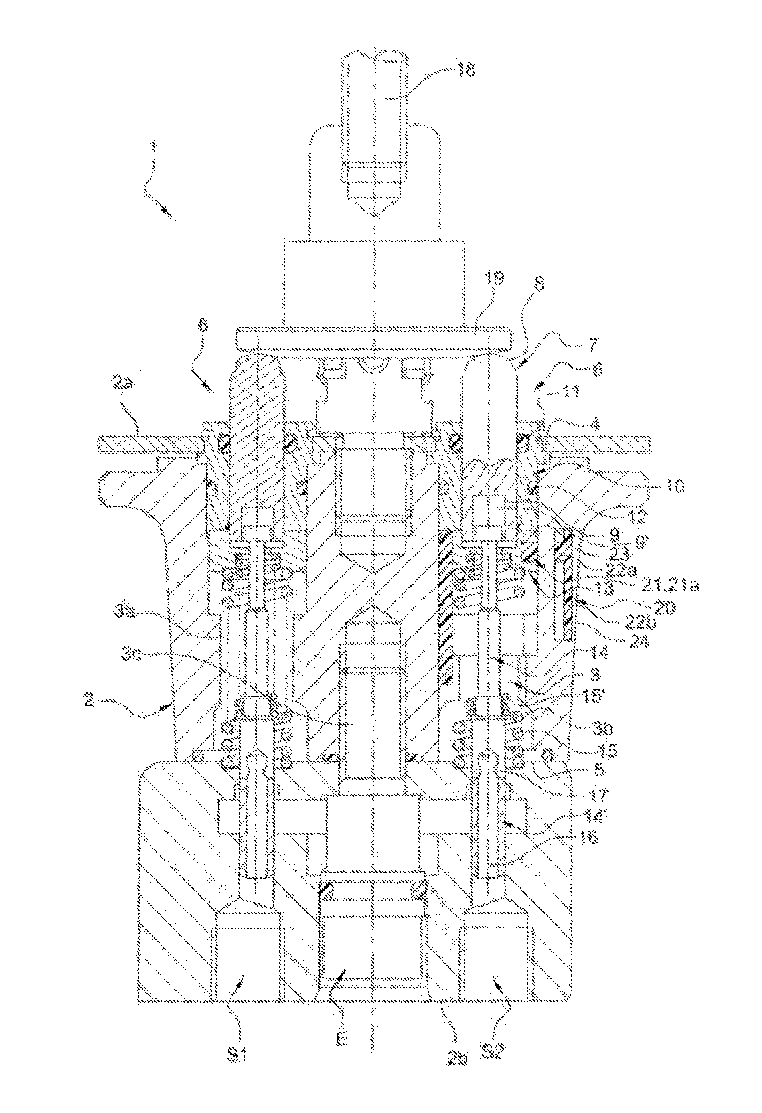
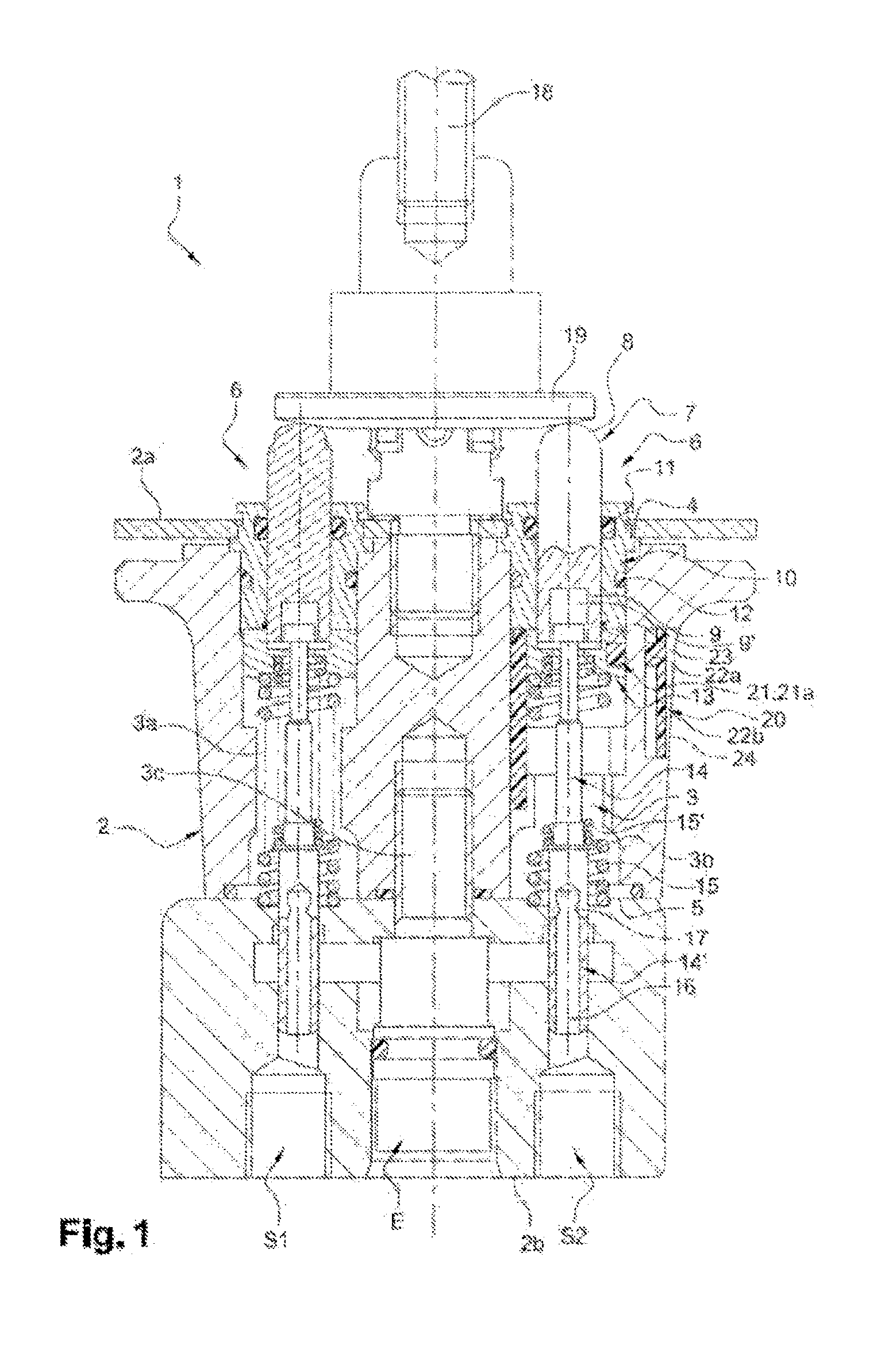
[0050]In the embodiments shown in FIG. 1, a pressure regulating device 1 includes a body 2 comprising two cavities 3a, 3b, extending between an end 4 opening onto an upper face 2a of the body 2 and a bottom 5 opening opposite to the end 4 opening onto a lower face 2b.

[0051]A third cavity 3c is, as for it, laid out so as to only open out onto the lower face 2b of the body 2 and to communicate via channels with each of the cavities 3a, 3b.

[0052]The third cavity 3c opening out onto the lower face 2b of the body 2 forms an entrance E for pressurized hydraulic fluid while both other cavities 2a, 2b opening out into the bottom 5 on the lower face 2b of the body each form an outlet S1, S2 for the regulated pressurized hydraulic fluid.

[0053]A fourth cavity (not shown), as for it, forms an outlet for the pressurized hydraulic fluid entering through the inlet E.

[0054]This cavity is connected to an outer hydraulic fluid tank, itself connected to a hydraulic pump bringing the pressurized hydr...


PUM


Abstract

The present invention relates to a pressure regulating device (1), in particular a hand- or foot-operated hydraulic controller for a heavy construction machine, characterised in that it comprises an electrical or electronic means (20) for determining the position of the actuator (18) or the push button (7) including a proportional sensor comprising, on the one hand, a mobile member (21) following the movement of the actuator (18) or a push button (7) and, on the other hand, a contactless means (22) for detecting the position of the mobile member (21) secured to the body (2), as well as an anti-tilting system, a load sensing system for controlling the pressure increase, the idling delivery of the heat engine, or a flow sharing system, comprising such a pressure regulating device (1).

Description

TECHNICAL FIELD[0001]The present invention relates to a pressure regulating device, notably a hand- or foot-operated controller for a public works machine, as well to as an anti-tilting system, a system for controlling the rise in pressure of the load sensing type, for leaving the idling mode of the heat engine or for the flow distribution of the flow sharing type, including such a device.BACKGROUND[0002]These pressure regulating devices are in particular used for ensuring the driving of various hydraulic functions such as setting various receiving members installed on-board these public works machines into motion.[0003]Such hydraulic distribution devices are well-known to one skilled in the arts and for example are described in document FR 2 376 978.[0004]The pressure regulating devices of the type described in the preceding document include a body comprising at least one cavity extending between an end opening onto at least one upper face of the body and a bottom opposite to the o...

Claims


Application Information

Patent Timeline
IPC IPC(8): F15B13/043
CPCF15B13/043Y10T137/86614F15B13/0424E02F9/2004G05G9/047G05G2009/04755G05G2009/04714F15B13/042F15B13/0422
Inventor MERLETTI, DIDIERBOUDOU, JEAN-LUC
Owner BOSCH REXROTH D S I
Why Eureka
Try Eureka