Apparatus for and method of controlling brakes

a technology of brakes and actuators, applied in the direction of brake systems, vehicle position/course/altitude control, instruments, etc., can solve the problems of reducing the operability of brakes, and reducing the controllability of wheel-cylinder pressure control. to achieve the effect of enhancing the total controllability of the brake control system

Inactive Publication Date: 2009-03-19
HITACHI LTD
View PDF7 Cites 48 Cited by
  • Summary
  • Abstract
  • Description
  • Claims
  • Application Information

AI Technical Summary

Benefits of technology

[0008]It is, therefore, in view of the previously-described disadvantages of the prior art, an object of the invention to provide an apparatus for and a method of controlling

Problems solved by technology

Thus, there is a problem of undesired interference between (i) the wheel-cylinder pressure buildup achieved by the driver's braking operation and (ii) the wheel-cylinder pressure buildup achieved by operating the fluid-pressure source, which interference may occur in both the master cylinder and the pressure-buildup control valve.
This leads to the reduced controllability for wheel-cylinder pressure control and the lowered operability for the brakes, in other words, a poor feel of the brake pedal on the automatic-braking-device equipped vehicle.
First, for instance during VDC control, suppose that the brake pedal is further depressed by the driver. In such a case, the master-cut valve is kept closed, and thus brake fluid cannot be supplied from the master cylinder to the wheel-brake cylinder without passing through the pump. It is difficult to directly reflect a driver's intention of increasing a vehicle deceleration rate (a negative longitudinal acceleration G), thereby lowering the controllability for wheel-cylinder pressure control. Additionally, at this time, the wheel-cylinder pressure (=the upstream pressure of the pressure-buildup control valve=the pump pressure) becomes higher than the master-cylinder pressure, thus causing a reduction in the pump inlet flow rate. This leads to the difficulty of providing a brake-pedal stroke, thereby resulting in a poor or uncushioned feel of the brake pedal on the automatic-braking-device equipped vehicle.
Secondly, suppose that BA control is initiated by operating the pump, simultaneously with a wheel-cylin

Method used


Image

  • Apparatus for and method of controlling brakes
  • Apparatus for and method of controlling brakes
  • Apparatus for and method of controlling brakes

Examples


first embodiment

[0038]Referring now to the drawings, particularly to FIG. 1, the brake control system of the first embodiment is exemplified in a four-wheeled automotive vehicle.

[0039][Hydraulic Circuit of Brake Control System]

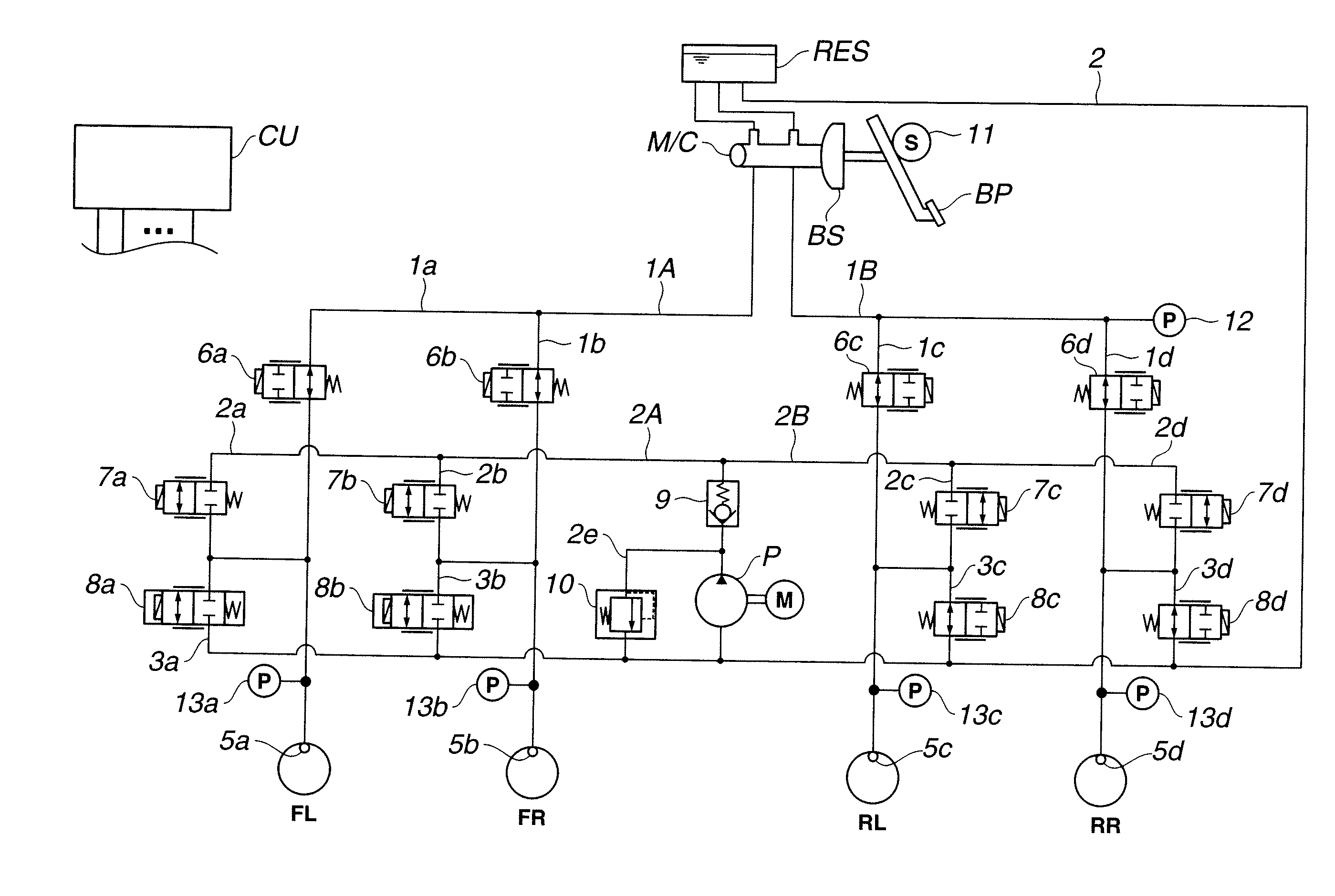
[0040]As seen in FIG. 1, the brake control system of the first embodiment includes a master cylinder MC whose piston rod is linked through a brake booster BS to a brake pedal BP, a fluid-pressure control unit (or a hydraulic control unit) HCU configured to supply a master-cylinder pressure to each of wheel-brake cylinders 5a-5d of front-left, front-right, rear-left, and rear-right road wheels FL, FR, RL, and RR, and an electronic control unit CU. Hydraulic control unit HCU includes a pump P, and a plurality of electromagnetic valves comprised of a plurality of first pressure-buildup control valves 6a-6d, which are collectively referred to as “first pressure-buildup control valve 6”, a plurality of second pressure-buildup control valves 7a-7d, which are collectively referred t...

second embodiment

Valve Arrangement of Second Embodiment

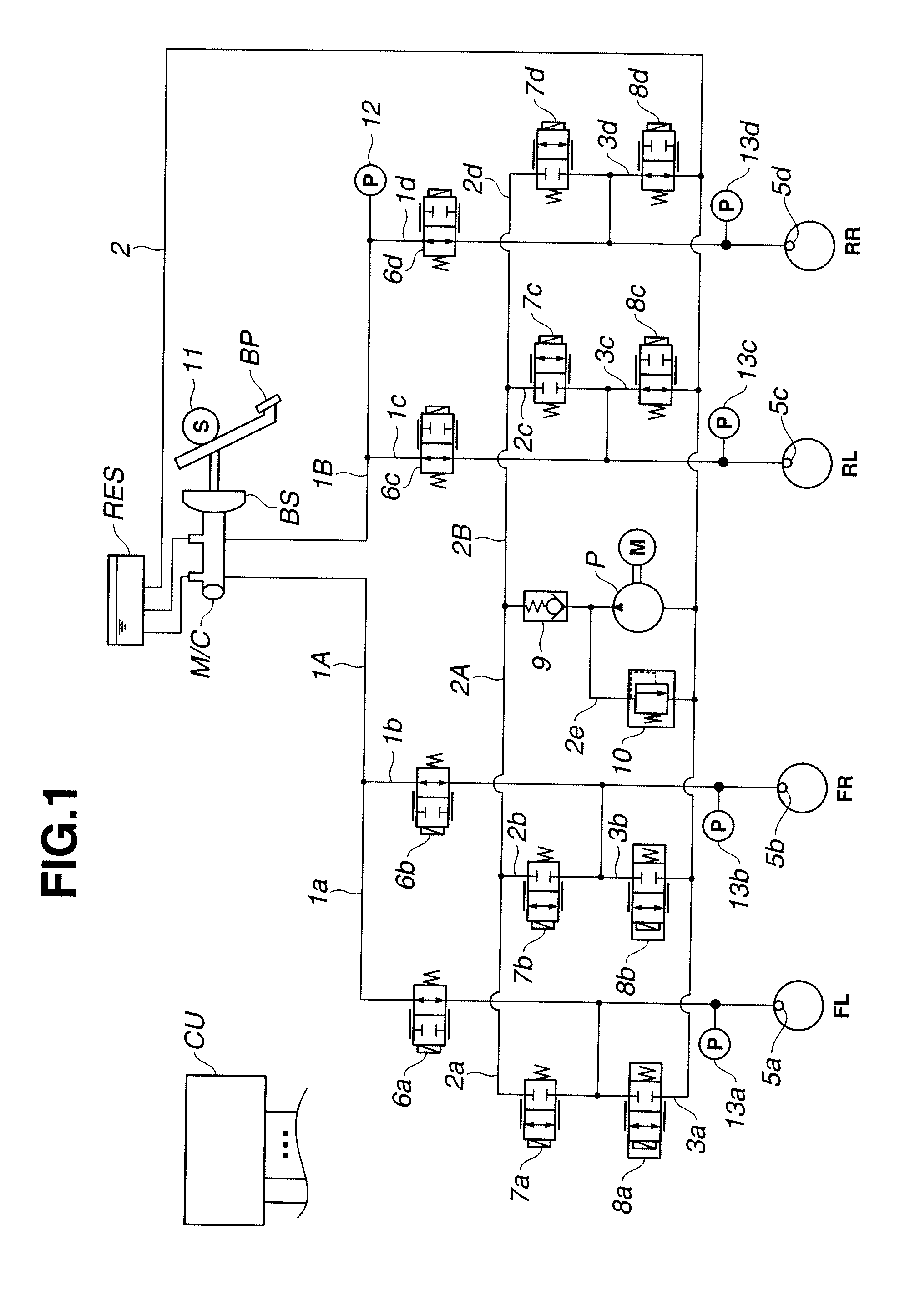
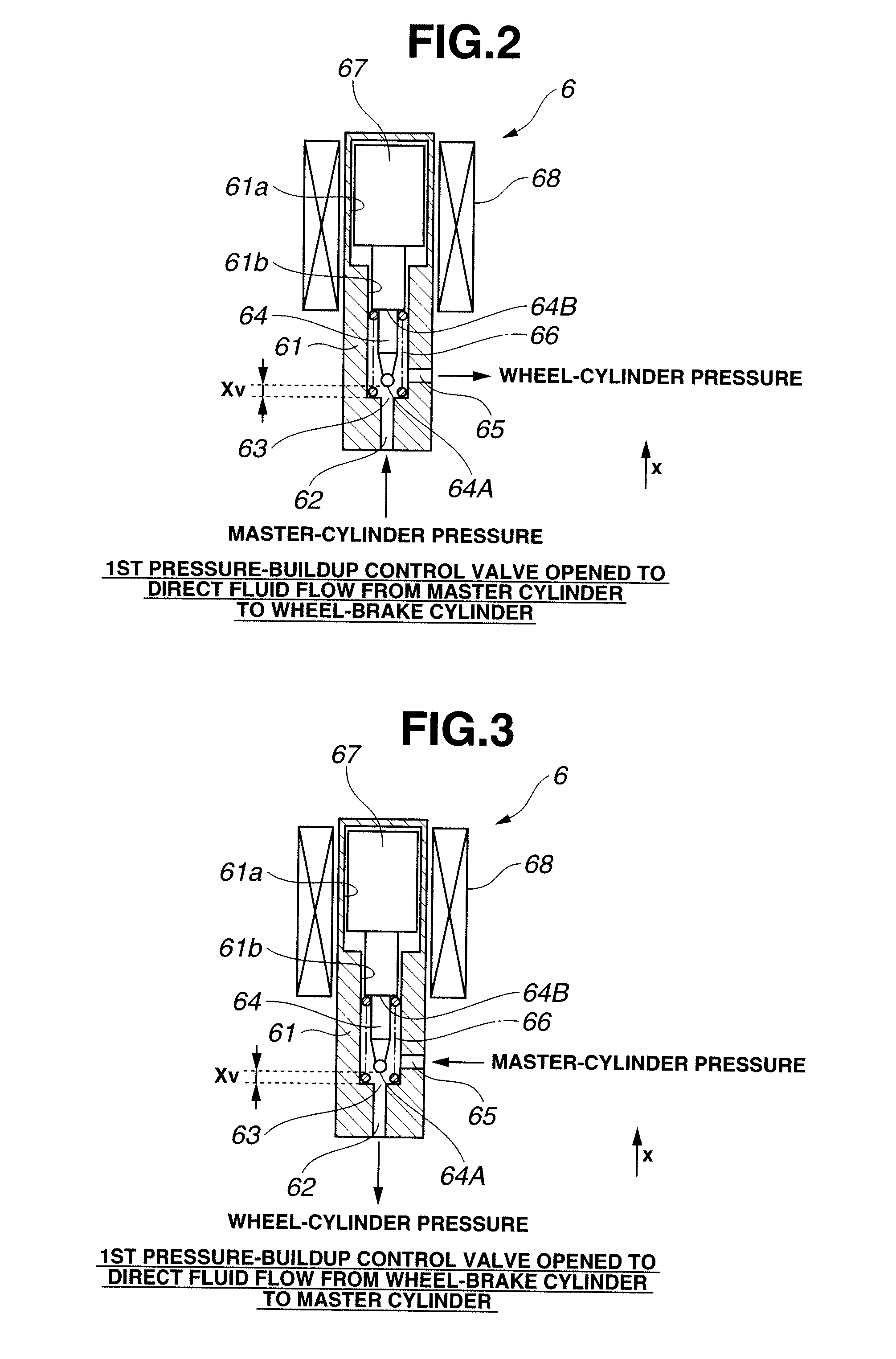
[0191]An apparatus for controlling brakes, made according to the second embodiment, has almost the same configuration of first pressure-buildup control valve 6 as the brake control apparatus of the first embodiment, but a direction of arrangement of each individual front-wheel side first pressure-buildup control valve 6a-6b and a direction of arrangement of each individual rear-wheel side first pressure-buildup control valve 6c-6d are reversed for the brake control apparatuses of the first and second embodiments. Concretely, in the second embodiment, first ports 62, 62 of first pressure-buildup control valves 6a-6b of the front-wheel side are connected to the respective downstream sides of fluid lines 1a-1b, and thus connected via fluid lines 1a-1b to respective front-wheel side wheel-brake cylinders 5a-5b. That is, first port 62 of each of front-wheel side first pressure-buildup control valves 6a-6b serves as a wheel-cylinder pressure port. On ...

third embodiment

BA Control of Third Embodiment

[0194]Referring now to FIG. 12, there is shown the flowchart concerning the wheel-cylinder pressure control routine executed by control unit CU, incorporated in the brake control apparatus of the third embodiment, during BA control. The control routine of FIG. 12 is also executed as time-triggered interrupt routines. The BA control routine of the third embodiment shown in FIG. 12 is similar to that of the first embodiment shown in FIG. 11, except that step S303 of FIG. 11 is replaced with step S303A of FIG. 12. Thus, the same step numbers used to designate steps in the routine shown in FIG. 10 will be applied to the corresponding step numbers used in the BA control routine shown in FIG. 11, for the purpose of comparison of the first and third embodiments. Step S303A will be hereinafter described in detail with reference to the accompanying drawings, while detailed description of steps S301, S302, and S304-S314 will be omitted because the above descripti...


PUM


Abstract

An apparatus for controlling brakes, includes a first brake circuit for supplying brake fluid, pressure-increased by a booster, to a wheel-brake cylinder, a first control valve disposed in the first brake circuit for establishing and blocking fluid communication between a master cylinder and the wheel-brake cylinder, a second brake circuit arranged in parallel with the first brake circuit for supplying brake fluid, pressure-increased by a fluid-pressure source, to the wheel-brake cylinder, and a second control valve disposed in the second brake circuit for establishing and blocking fluid communication between the fluid-pressure source and the wheel-brake cylinder. Also provided is a control unit, which is configured to selectively control the first and second control valves when building-up wheel-cylinder pressure, and further configured to build-up the wheel-cylinder pressure by operating the fluid-pressure source when at least the second control valve is controlled to a valve-open position.

Description

TECHNICAL FIELD[0001]The present invention relates to an apparatus for and a method of controlling each wheel-brake cylinder pressure of an automotive vehicle, based on a driver's braking operation and / or a vehicle traveling state.BACKGROUND ART[0002]In recent years, there have been proposed and developed various automatic braking devices. One such braking device has been disclosed in Japanese Patent Provisional Publication No. 2004-9914 (hereinafter is referred to as “JP2004-009914”). FIG. 25 is a hydraulic circuit diagram showing a hydraulic system configuration of the braking device as disclosed in JP2004-009914 (a comparative example). The braking device shown in FIG. 25 is configured to build up each wheel-brake cylinder pressure, directly, by using a brake-fluid pressure produced by a driver's braking operation at a normal brake mode, and also to perform automatic wheel-cylinder pressure control (simply, automatic brake control) by using a pump discharge pressure. Such automat...

Claims


Application Information

Patent Timeline
IPC IPC(8): B60T8/34B60T7/12
CPCB60T8/3275B60T8/367B60T2201/03B60T8/4827B60T13/662B60T8/4072
Inventor OOSAWA, TOSHIYAISWASAKI, KATSUYA
Owner HITACHI LTD
Why Eureka
Try Eureka