Friction lining carrier plate

a technology of friction lining and carrier plate, which is applied in the direction of friction lining, actuators, brake types, etc., can solve the problems of high weight of friction lining carrier plate and thick sheet steel, and achieve the effect of reducing the amount of friction lining, less friction lining material, and reducing the total weight of friction lining

Inactive Publication Date: 2013-10-24
TMD FRICTION SERVICES +1
View PDF9 Cites 9 Cited by
  • Summary
  • Abstract
  • Description
  • Claims
  • Application Information

AI Technical Summary

Benefits of technology

[0013]Another advantage of the invention lies in the fact that the use of at least two depressions of different depths can reduce the amount of friction lining used in comparison to a friction lining carrier plate that only has one single depression, provided that the thickness of the two friction lining carrier plates is the same. The reason for this is that the first and second depressions have different depths. The depth of the first depression is less than that of the second depression or vice versa. As a result, less friction lining material is needed since, due to the smaller depth of the first depression, less friction lining material is needed in order to fill the first and second depressions than would be the case if a friction lining carrier plate were provided with only one depression having a constant depth. As a result, friction material on the front of the friction lining carrier plate is displaced by the depressions created by shaping on the rear of the friction lining carrier. Consequently, the total weight of the friction lining is reduced. In addition, due to the depressions that have been thus created, the friction lining carrier plate acquires greater flexural and torsional stiffness. Moreover, the use of a friction lining carrier plate made of a thinner material translates into a smaller installation volume while the wearing volume remains the same. The friction lining material and / or an interlayer can be applied onto the friction lining carrier plate, for example, by means of an adhesive.
[0014]The friction lining carrier plate for the second depression can be embossed at those places of the friction lining carrier plate that, on the side where the actuation means is located, can be brought into contact with other parts such as, for instance, a brake piston. In this context, the embossing of the friction lining carrier plate is carried out in such a way that the second depression is of such a depth on the side where the friction lining is located or has such a high second elevation on the side where the actuation means is located that it is ensured that, for example, the actuation means can come into contact with the second elevation during the braking process.
[0015]In a preferred embodiment of the invention, a material having a lower thermal conductivity than that of the friction lining can be placed into the first and / or second depression. This reduces the heat conveyed to the actuation means during the braking process, as a result of which the risk of damage to the actuation means is lowered.
[0016]Thanks to the fact that the first and second depressions have been provided, the local thickness of the friction lining that is placed into the first and second depressions can be set. Thus, at the places where the friction lining has been installed in the first and second depressions, the friction lining is thicker than at the places where it has only been installed in the first depression, or else, on the side where the friction lining carrier plate is located, the friction lining has first and second elevations that penetrate into the first and second depressions when the friction lining is in its installed state. In this context, the first and second elevations are configured in such a manner that they extend to different extents in the direction of the friction lining carrier plate.
[0017]Due to the local thickness of the friction lining or due to the different extensions of the first and second elevations, an adjustable spring effect, and thus flexibility of the friction lining, can be achieved. By setting the local thickness of the friction lining, it can be achieved that the tendency towards crack formation of the friction lining is reduced since the brake lining has a greater overall flexibility. Furthermore, a more uniform introduction of heat into a brake disc and / or friction lining carrier plate can be achieved due to the better contact of the friction lining with the brake disc. This reduces the tendency towards crack formation of the brake disc. Owing to the adjustable spring effect of the friction lining, greater damping, especially greater local damping, can be achieved during a braking process. This brings about a noise reduction during the braking process. Moreover, by setting the local thicknesses, it is possible to systematically set the compressibility of the friction lining by means of the thickness of the friction lining. In other words, the friction lining can be set so as to be harder. Setting the compressibility by means of the thickness of the friction lining translates into greater comfort since there are fewer changes in the compressibility over the service life of the friction lining. In addition the second depression can be provided at those places of the friction lining carrier plate where it is needed in order to set the local thickness of the friction lining.
[0018]Another advantage of providing a friction lining with different thicknesses, or else with first and second elevations, consists of the fact that, while the installation volume and the wearing volume remain the same, the friction lining has a smaller mass than friction linings that are of the same thickness or only have one elevation.

Problems solved by technology

One drawback of the known friction lining carrier plates is that the sheet steel is thick, as a consequence of which the friction lining carrier plate is very heavy.

Method used


Image

  • Friction lining carrier plate
  • Friction lining carrier plate
  • Friction lining carrier plate

Examples


Embodiment Construction

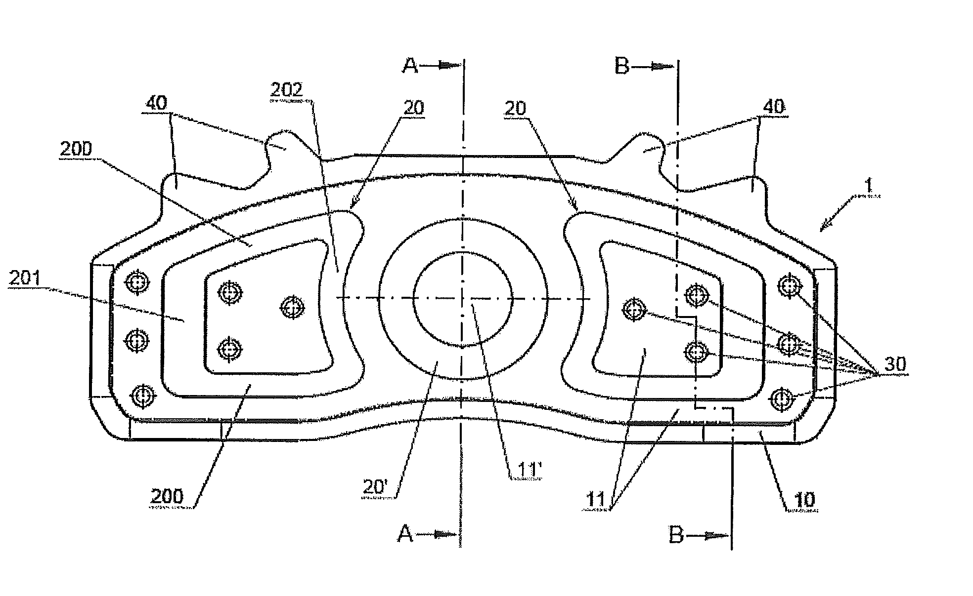
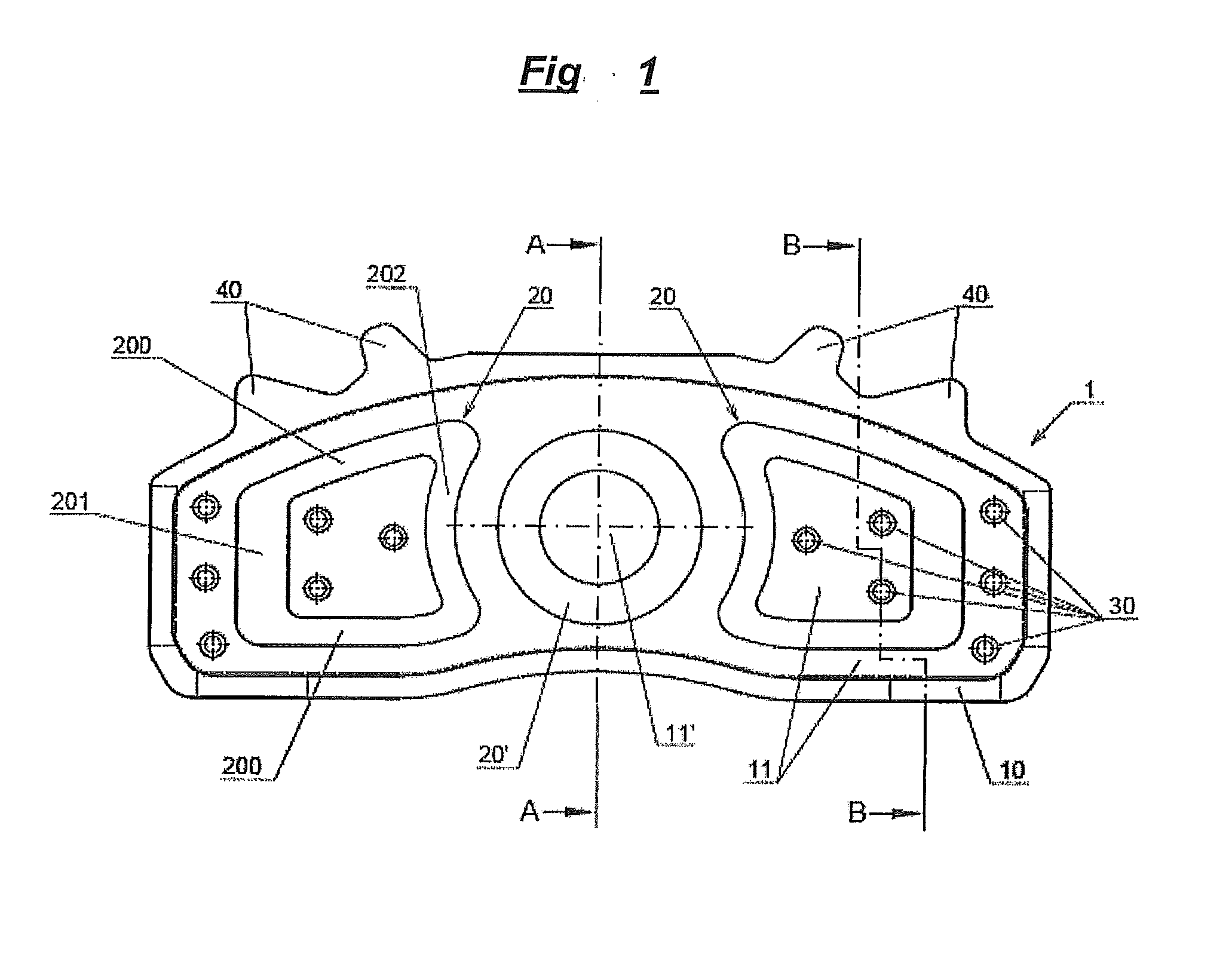
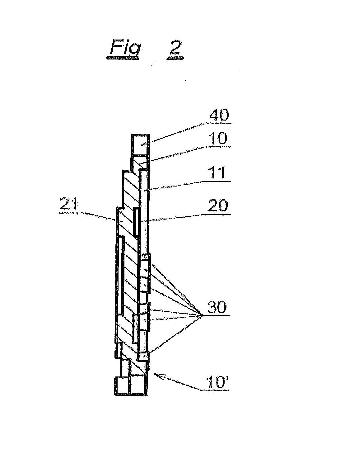
[0037]The friction lining carrier plate 1 shown in FIG. 1 has several fastening means 40 for fastening the friction lining carrier plate 1 to a brake system (not shown here). Moreover, on the side where the friction lining is located, the friction lining carrier plate 1 has a web 10 that runs along the edge of the friction lining carrier plate, a first depression 11 and two differently configured depressions 20, 20′. The web 10 extends from the first depression 11 in the direction away from the rear of the friction lining carrier plate 1. Moreover, the friction lining carrier plate 1 has several projections 30 which extend from the bottom of the first depression 11 in the direction away from the rear of the friction lining carrier plate 1.

[0038]A second depression 20′ is configured so as to be circular and it surrounds a circular first depression 11′. The width of the second circular depression 20 is constant and preferably amounts to 10 mm. The circular second depression 20′ is arr...


PUM

PropertyMeasurementUnit
thicknessaaaaaaaaaa
thicknessaaaaaaaaaa
thicknessaaaaaaaaaa

Abstract

The invention relates to a friction lining carrier plate (1), which has a metal sheet, to a friction lining, to a friction lining receptacle and to a brake. The metal sheet is formed in such a manner that it has a first and second recess (11, 20) on the friction lining side, wherein the metal sheet has at least a second recess (20) on the friction lining side, wherein the first and second recesses (11, 20) have a differing depth. The first and second recesses on the friction lining side are each formed as an elevation on the side of the actuation means.

Description

CROSS-REFERENCE TO RELATED APPLICATIONS [0001]This application is a national stage application (under 35 U.S.C. §371) of PCT / EP2012 / 130587, filed Mar. 9, 2012, which claims benefit of German application 10 2011 001 562.0, filed Mar. 25, 2011.TECHNICAL FIELD AND STATE OF THE ART [0002]The state of the art encompasses differently configured friction lining carrier plates, for example, for disc brakes onto which a friction lining is applied.[0003]Certain prerequisites have to be met whenever new friction lining carrier plates are designed. For instance, the friction lining carrier plate has to be configured in such a way that it is ensured that the friction lining cannot become detached. Moreover, the friction lining carrier plate has to be configured in such a way that it has the same envelope contour as existing friction lining carrier plates, so that the friction lining carrier plate can be installed in existing brake systems.[0004]International patent document WO 2010 / 128133 disclo...

Claims


Application Information

Patent Timeline
Patent Type & Authority Applications(United States)
IPC IPC(8): F16D65/095F16D65/092
CPCF16D65/095F16D65/092F16D2069/0441F16D2200/0021B21D22/04F16D69/0408
Inventor BORGMEIER, OLAVDRESEN, DIRKGRZANNA, HARALDHOGENKAMP, WOLFGANGKIERSPEL, THOMASMUHL, ARMINROHLING, WILLMUTSAKAGUCHI, DAI-VICTORSTEEGE, ROLANDASBECK, JOCHENHAHNER, CHRISTOPH
Owner TMD FRICTION SERVICES
Why Eureka
Try Eureka