
Nanostrong vibratory screens & separators

a vibratory screen, strong technology, applied in the direction of solid separation, material nanotechnology, chemistry apparatus and processes, etc., can solve the problems of wear and tear of the screen, and achieve the effect of enhancing conductivity, sacrificing the needed strength, and enhancing conductivity

Inactive Publication Date: 2013-10-24
MCCLUNG III GUY L
View PDF2 Cites 34 Cited by
  • Summary
  • Abstract
  • Description
  • Claims
  • Application Information

AI Technical Summary

Benefits of technology

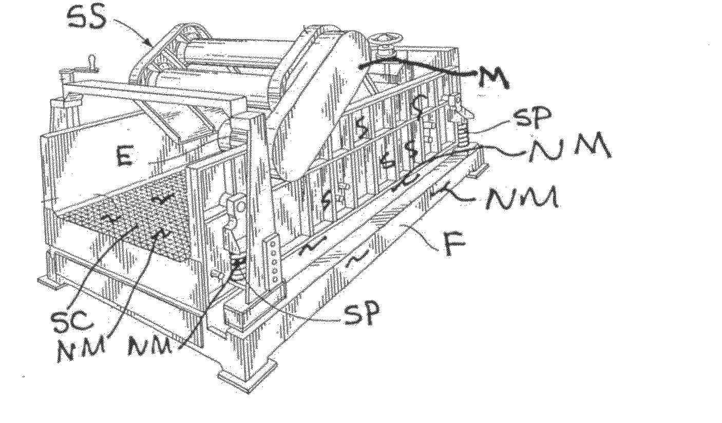
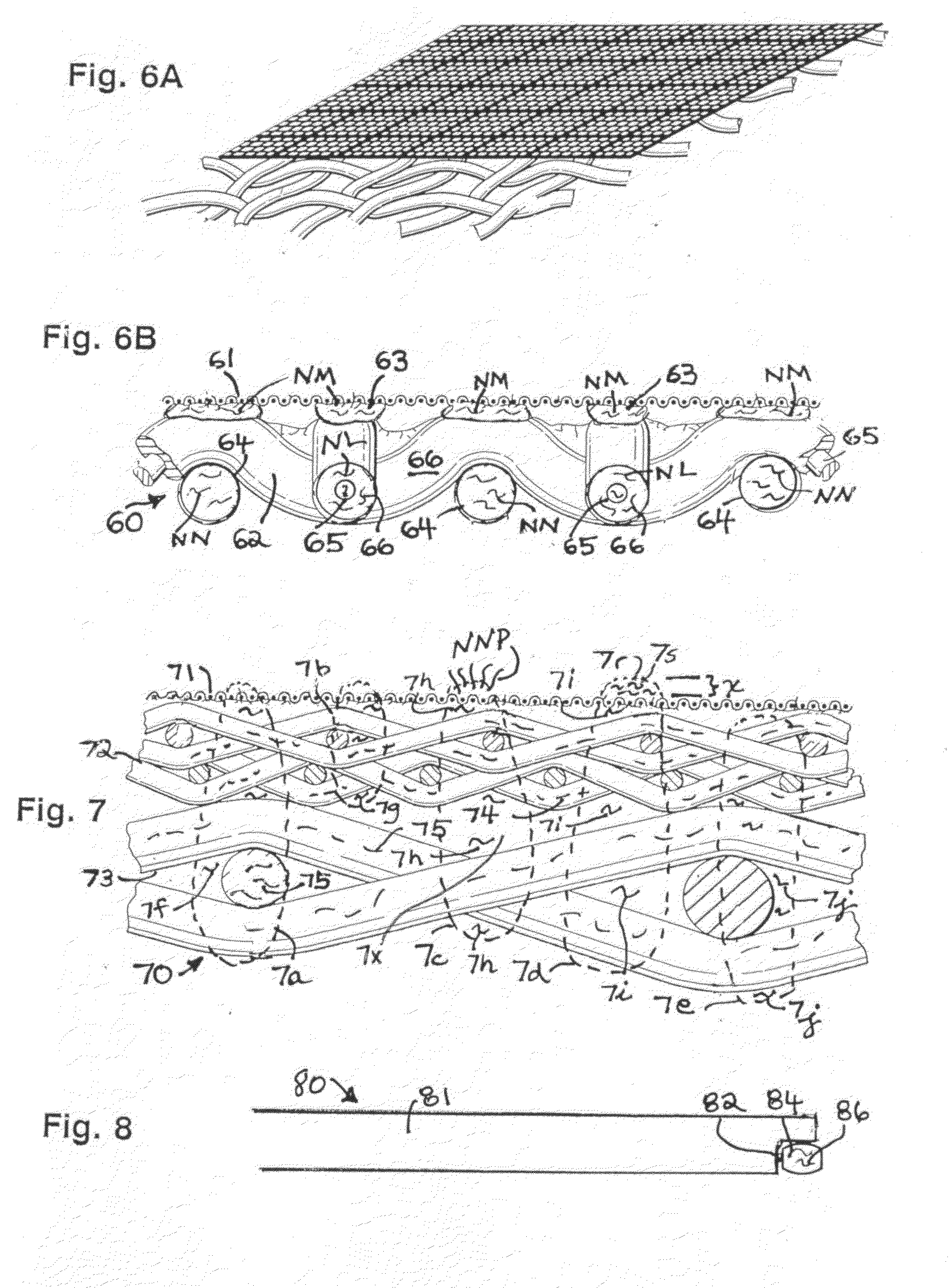
The present invention provides a screen assembly for a vibratory separator or shale shaker that includes a support with nanomaterial strengtheners and adhesive containing nanomaterial to connect screening material to the support. The use of nanomaterial strengtheners allows for the use of smaller amounts of adhesive, which results in more open screening area for the material to be treated by the separator or shaker. The use of supports with larger openings without sacrificing their strength to withstand the forces imparted by the vibratory motors of separators and shakers is also possible. The invention also provides an erosion resistant surface for parts of a vibratory separator or shaker that come into contact with the material being treated, resulting in improved durability.

Problems solved by technology

At some point, due to screen wear and degradation, and sometimes due to damage to a screen, screens are periodically replaced.
Fluid alone and / or abrasives and solids in some fluids can wear away parts of a screen, e.g., a screen support and / or screening material itself.

Method used


Image

  • Nanostrong vibratory screens & separators
  • Nanostrong vibratory screens & separators
  • Nanostrong vibratory screens & separators

Examples


Embodiment Construction

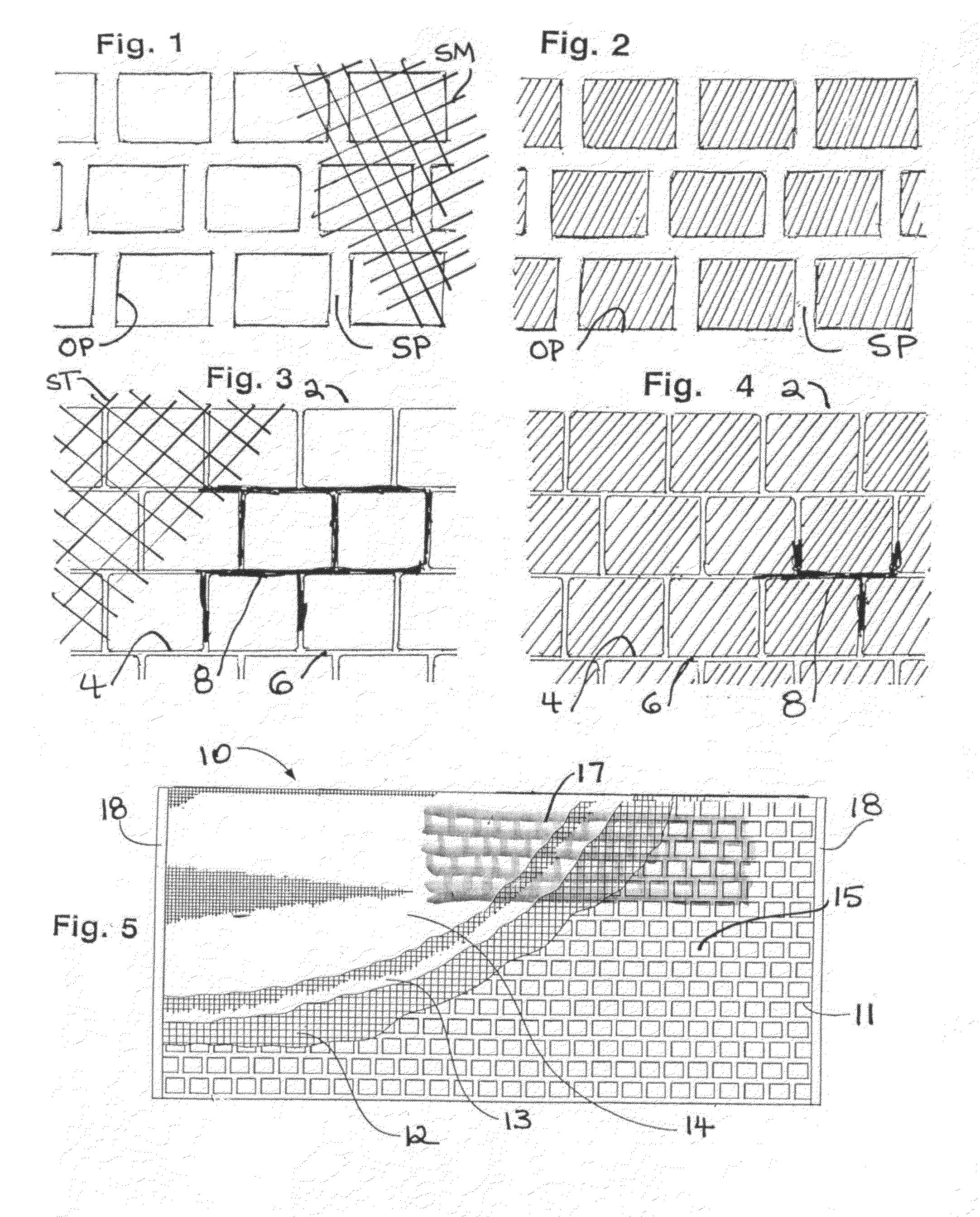
[0103]FIGS. 1 and 2 illustrate openings OP in a screen support SP (shown partially). The openings have a measurable opening area and the amount of the support mass between openings is also measureable. A component or components of material, e.g., fluid or slurry, to be treated by a separator or shaker with a screen with a support like the support SP can flow to and through screening material SM (shown partially, FIG. 1) over the openings OP. Such component(s) cannot flow through the screen support mass around the openings. Some components (or a component) pass through the screening material SM. It is within the scope of the present invention, for a screen according to the present invention to have a support according to the present invention with the dimensions, openings, and spacing of the support SP.

[0104]FIGS. 3 and 4 illustrate a screen support 2 according to the present invention with openings 4 therethrough. The screen support 2 has amounts of its mass 6 between the openings 4...


PUM


Abstract

Vibratory separators, shale shakers, screens, and screen assemblies, and screening material with nanomaterial thereon and / or therein for strengthening, conductivity enhancement, or both, and methods of using such things. This abstract is provided to comply with the rules requiring an abstract which will allow a searcher or other reader to quickly ascertain the subject matter of the technical disclosure and is submitted with the understanding that it will not be used to interpret or limit the scope or meaning of the claims, 37 C.F.R. 1.72(b).

Description

RELATED APPLICATION[0001]The present invention and this application claim the benefit of priority under the patent Laws of U.S. Application Ser. No. 61 / 633,980 filed Feb. 21, 2012, said application incorporated fully herein for all purposes.BACKGROUND OF THE INVENTION[0002]1. Field of the Invention[0003]The present invention is directed to: vibratory separators; screens used with them; shale shakers; screens used with them; frames, supports, grids, strips, and plates for such screens; adhesives for use with such screens; materials and methods for making such screens and such frames, etc.; and materials for such screens and frames, etc. with nanomaterial thereon and / or dispersed therein for strength and / or for enhanced conductivity (thermal, electric, of mechanical force).[0004]2. Description of Related Art[0005]Vibratory separators are used in a wide variety of industries to separate materials such as liquids from solids, solids from slurries, solids from fluids, or solids from soli...

Claims


Application Information

Patent Timeline
Patent Type & Authority Applications(United States)
IPC IPC(8): B07B1/46B07B1/34
CPCB07B1/46B07B1/34Y10S977/902B82Y30/00B07B1/4672
Inventor MCCLUNG, III, GUY L.
Owner MCCLUNG III GUY L
Learn More