Although such conventional handles are inexpensive to produce, they suffer from a variety of drawbacks.
They are easy to
mount to the tray by flexing the end portions and inserting them into the tray openings but the handles do not remain securely engaged in the tray openings.
That is because, if the handle end portions are made to be very flexible for easy
insertion into the tray openings, they tend to accidently dislodge from the tray openings when the tray is picked up by the handle, particularly when the tray is heavily weighted with soil and plants.
On the other hand, if the end portions of the handle are made less flexible, so as to more securely engage the tray, it becomes more difficult and
time consuming to properly insert the end portions into the tray openings in the proper position.
The conventional handles are particularly difficult to
mount to the tray at certain times during the growing cycle of the plants.
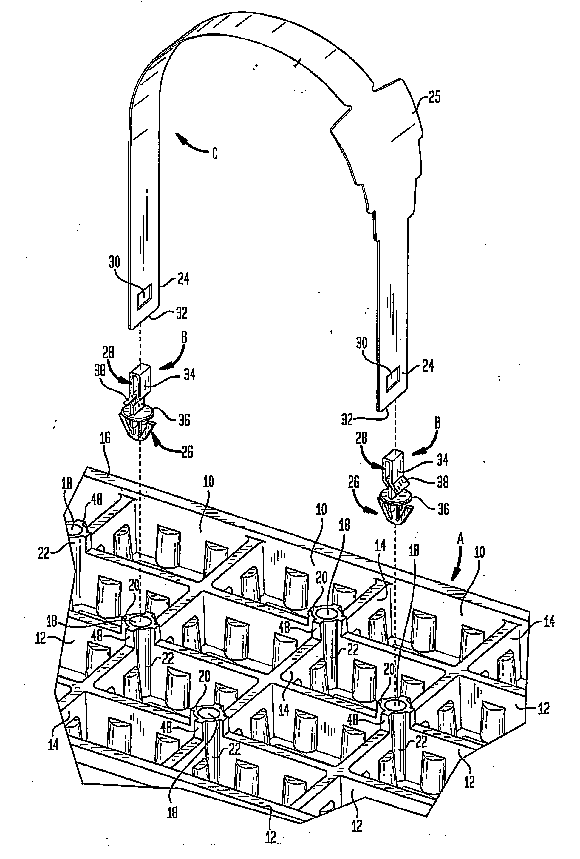
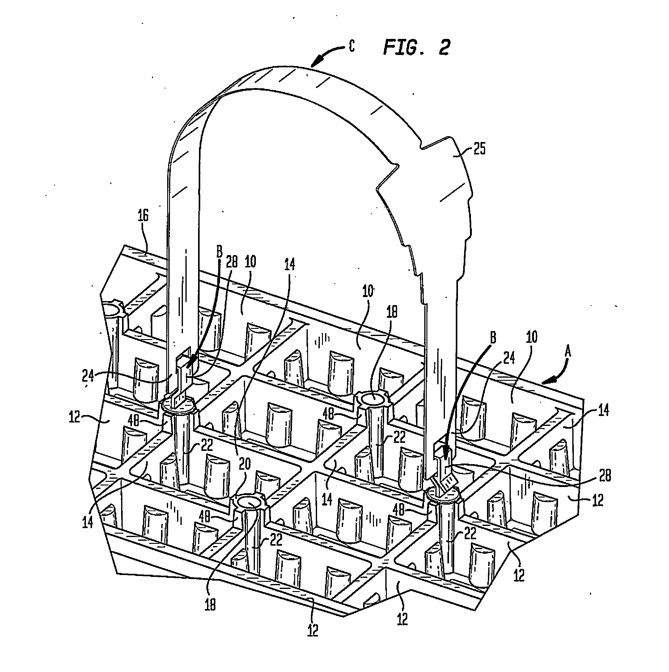
Due to high transportation costs, empty trays are transported in multi-unit stacks from the manufacturer to the location where the plants seedlings are inserted into the soil in the tray cells to grow.
Because the openings in the tray into which the handle end portions are received are located in the plane of the top surface of the tray, once the plants grow above that plane, the openings may become partially or completely obscured by the plants.
It is then often difficult for the person mounting the handles to locate the openings in order to insert the end portions of the handles.
The result is that the handle mounting process is more
time consuming and the plants may be damaged during the handle mounting process.
Otherwise, the handle may dislodge when the tray is picked up.
Accordingly, the mounting procedure is labor intensive and requires substantial time to complete successfully.
As a result, once mounted, the handle is not fixed in the upright position and the handle may move to a position in which it cannot be easily grabbed.
With conventional handles, it is virtually impossible to carry more than one tray in each hand and thus an individual can carry two trays at most.
If one does try to carry more than one tray in a single hand, the trays must be held at an awkward angle and the end portions of the handle may dislodge because of the extra force applied to them.
This becomes a particularly troublesome problem at retail when a
consumer wishes to purchase more than two trays.
Because the
consumer can only carry two trays at a time, often the
consumer will buy only two, limiting the number of trays that are sold.
However, that is often not the case with conventional handles because of the size and the position of the openings in the tray.
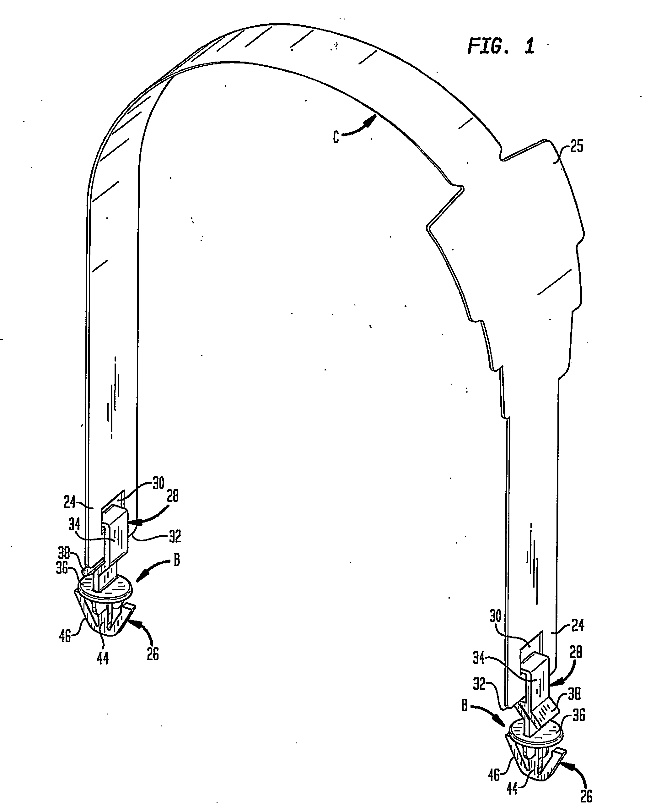
With conventional handles, there is no structure to keep the handle end portions centered within the tray openings.
Movement of an end portion from a position at the center of a tray opening may result in accidental detachment of the handle from the tray.
