Solenoid valve with a piston damped armature

a solenoid valve and piston technology, applied in the direction of valve details, valve arrangement, valve operating means/releasing devices, etc., can solve the problems of force being added to the armature and limited flow

Inactive Publication Date: 2013-10-24
HUSCO AUTOMOTIVE HLDG
View PDF2 Cites 9 Cited by
  • Summary
  • Abstract
  • Description
  • Claims
  • Application Information

AI Technical Summary

Benefits of technology

[0012]When the armature moves at low velocity, such as occurs upon movement from a steady state position, the pressure increases in either the first or second chamber causing fluid to flow from that chamber through the damping orifice in the damping piston. This reduces the effects of the pressure increase allowing the armature to move. At this time, the damping piston remains relatively stationary with respect to the armature. Thus, the damping spring does not contribute any force that damps the armature motion. This enables the armature and the associated valve element to be accurately positioned.
[0014]Thus at low armature velocities, the damping effect is due essentially to the flow restriction provided by the damping orifice and at higher velocities, the dampening spring and motion of the damping piston primarily provide the damping effect.
[0015]In one aspect of the present invention, the damping spring biases the damping piston into a normal position when the electrohydraulic valve is in a steady state, and allows the damping piston to move bidirectionally from the normal position.

Problems solved by technology

As a result of the damping piston movement, there is limited flow through the damping orifice and a minimal pressure differential across the damping piston and the armature.
The lack of a significant pressure differential means that the force being added to the armature comes primarily from the damping spring.

Method used


Image

  • Solenoid valve with a piston damped armature
  • Solenoid valve with a piston damped armature
  • Solenoid valve with a piston damped armature

Examples


Embodiment Construction

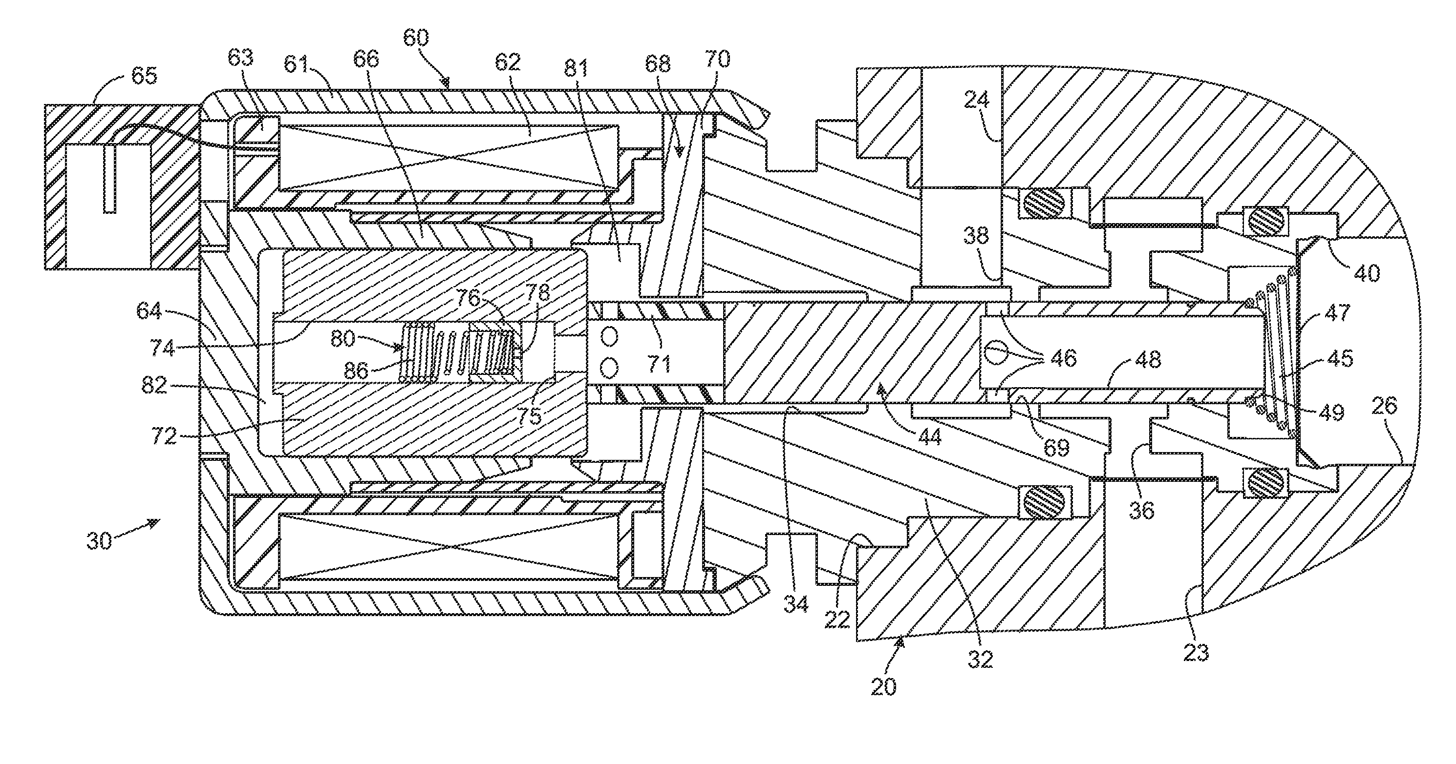
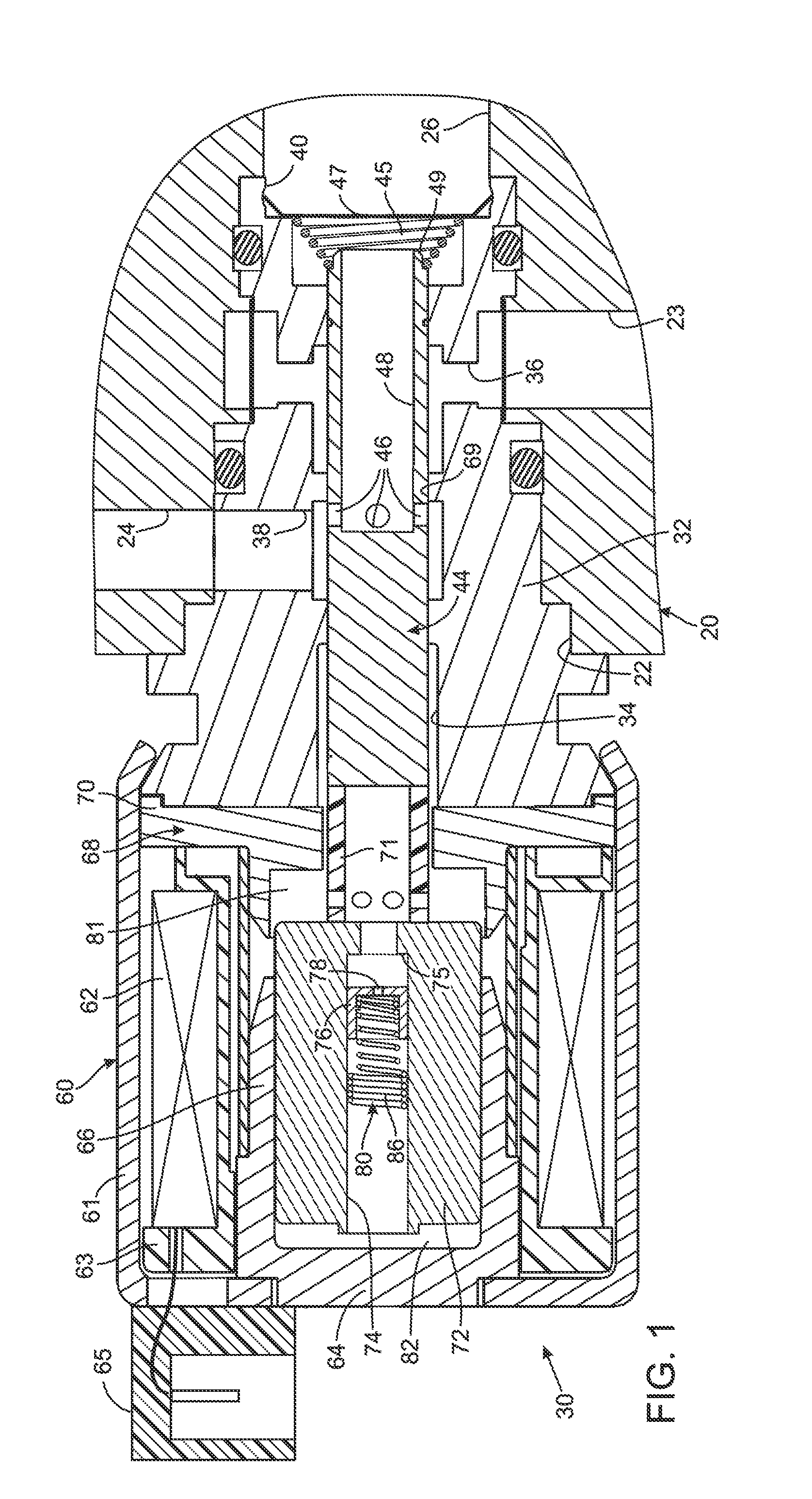
[0019]References herein to directional movement, such as left or right, refer to the motion of the components in the orientation illustrated in the drawings, which may not be the orientation of the components or the present control valve when attached to a machine.

[0020]With initial reference to FIG. 1, an electrohydraulic first control valve 30 is illustrated inserted into an aperture 22 in a manifold 20. The manifold 20 has a supply passage 23 that conveys pressurized fluid from a source such as a pump (not shown) and a return passage 24 that conveys fluid back to a tank (not shown). The manifold 20 also has a device passage 26 to which is connected a hydraulic component that is controlled by the first control valve 30.

[0021]The first control valve 30 has a tubular valve body 32 with a longitudinal bore 34 and transverse openings which provide ports between the manifold passages and the longitudinal bore. Specifically, the longitudinal bore 34 is connected by a supply port 36 to t...


PUM


Abstract

A valve has a body with two ports and a valve element for controlling fluid flow between those fluid ports. A solenoid actuator includes a moveable armature operatively coupled to the valve element and defining first and second chambers on opposite sides of the armature. A bore extends through the armature between those chambers. A damping piston, slideably located in the bore, has a damping orifice forming a continuously open path there through. A spring biases the damping piston into a normal position in a steady state of the valve and allows bidirectional armature motion therefrom. When the armature moves at low velocity, a pressure increase in one chamber is relieved by flow through the damping orifice. As the armature velocity increases, so too does pressure in the one chamber, causing the damping piston to move relative to the armature, thereby adding damping force from the spring to the armature.

Description

CROSS-REFERENCE TO RELATED APPLICATIONS[0001]Not ApplicableSTATEMENT REGARDING FEDERALLY SPONSORED RESEARCH OR DEVELOPMENT[0002]Not ApplicableBACKGROUND OF THE INVENTION[0003]1. Field of the Invention[0004]The present invention relates to solenoid operated hydraulic valves and in particular to techniques for damping the operation of such valves.[0005]2. Description of the Related Art[0006]Electrohydraulic valves have been developed for a variety of equipment to selectively apply and exhaust pressurized fluid to and from a component, the operation of which is controlled by that valve. One type of such valve has a spool that slides within a bore. In one position, the spool provides a path between a supply conduit containing pressurized fluid to a workport that is connected to the component being operated by the valve. In another position, the spool provides a path between the workport and an exhaust port to relieve pressure at the workport. In a third position of the spool, the workpo...

Claims


Application Information

Patent Timeline
Patent Type & Authority Applications(United States)
IPC IPC(8): F16K31/02
CPCF16K31/0613F16K31/0686F16K31/0693
Inventor VAN WEELDEN, CURTIS L.
Owner HUSCO AUTOMOTIVE HLDG
Why Eureka
Try Eureka