Coil unit, substrate unit and power supply device

a power supply device and substrate technology, applied in the field of coil units, can solve the problem of large size of coil components, and achieve the effect of easy connection

Active Publication Date: 2013-10-24
TDK CORPARATION
View PDF2 Cites 6 Cited by
  • Summary
  • Abstract
  • Description
  • Claims
  • Application Information

AI Technical Summary

Benefits of technology

The present invention is about a coil unit that allows for easy connection of stacked print coils. It also includes a substrate unit that holds the coil unit and a power supply device. The purpose of this invention is to provide a more efficient and reliable connection for coil units in printing equipment.

Problems solved by technology

Therefore, in an attempt to prepare a coil component large in capacity or step-up or step-down ratio, the coil component is made larger in size, which poses a problem.

Method used


Image

  • Coil unit, substrate unit and power supply device
  • Coil unit, substrate unit and power supply device
  • Coil unit, substrate unit and power supply device

Examples


Embodiment Construction

[0040]Hereinafter, a detailed description will be given of an embodiment for executing the present invention with reference to the attached drawings. In describing the drawings, the same reference signs will be given to the same constituents, with overlapping description omitted here.

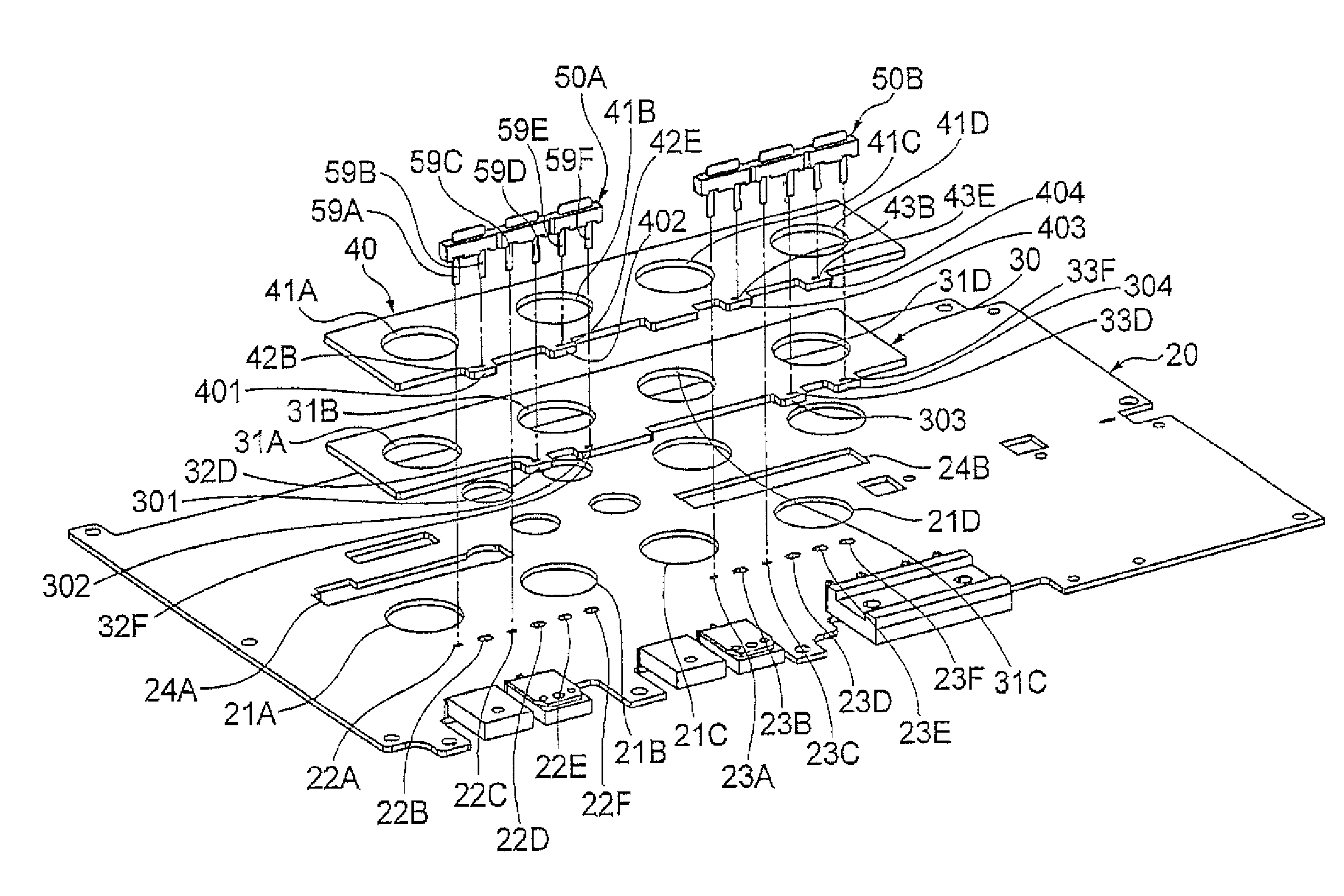
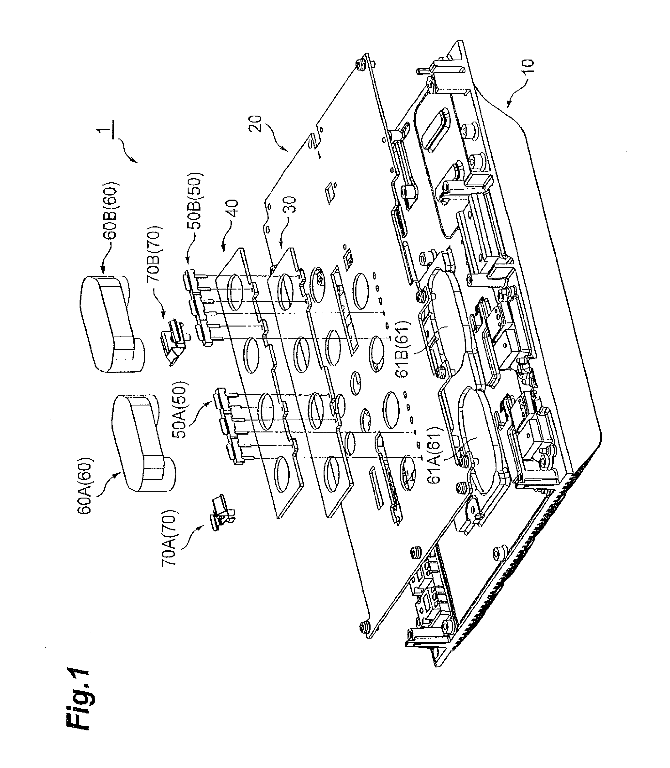
[0041]FIG. 1 is an exploded perspective view which describes a general constitution of the power supply device of the present embodiment. The power supply device 1 of the present embodiment is constituted so as to include a casing 10, a main circuit substrate 20, a print-coil substrate 30 (primary print-coil substrate), a print-coil substrate 40 (secondary print-coil substrate), U-shaped terminals 50 (50A, 50B), ferrite cores 60 (60A, 60B), 61 (61A, 61B), and spring supports 70 (70A, 70B). The power supply device 1 is constituted in such a manner that individual components constituting the power supply device including the main circuit substrate 20 on which a control circuit and the like are placed are ...


PUM


Abstract

In the coil unit 1A of the power supply device 1, the U-shaped plate 51C constituting the U-shaped terminal 50 is used to electrically connect the print-coil substrates 30, 40. Further, the print-coil substrates 30, 40 constituting the coil unit 1A can be connected to the main circuit substrate 20 also by using the U-shaped terminal 50. Here, the print-coil substrate 30 is connected to the print-coil substrate 40 by using the U-shaped terminal 50, by which soldering for fixing the U-shaped terminal 50 is performed from the lower face side of the print-coil substrate 30. Therefore, as compared with a conventional constitution where soldering is performed from both sides of the stacked print-coil substrates, the print coils can be connected by soldering only from one side face, thus making it possible to reduce the amount of work necessary for connecting the print coils.

Description

BACKGROUND OF THE INVENTION[0001]1. Field of the Invention[0002]The present invention relates to a coil unit which is composed of stacked print coils, a substrate unit in which the coil unit is mounted on a main circuit substrate and a power supply device which is constituted so as to include the substrate unit.[0003]2. Related Background Art[0004]The power supply device is constituted with a semiconductor which serves as a switching element, coils such as a transformer and an inductor in which a ferrite core is used, a main circuit substrate which is electrically and mechanically connected to these electronic components, a control substrate which controls the electronic components, and the like.[0005]Of these electronic components, in a coil component obtained by winding a coil around the core, an increase in capacity requires the coil width to be thick so as to withstand a high current or large current. Further, in order to increase step-up or step-down ratio between primary and s...

Claims


Application Information

Patent Timeline
IPC IPC(8): H01F5/00
CPCH01F5/003H01F27/2804H01F27/306H01F2027/2819
Inventor HARA, YASUHIROSATO, MASAKIMISONO, TORAONAKAHORI, WATARUSANAE, HARUHIKO
Owner TDK CORPARATION
Why Eureka
Try Eureka