
Display panel having non-uniform pixel distribution density

a display panel and distribution density technology, applied in the field of display panels, can solve the problems of coarse images, shrinking the pixel size of the display panel, and increasing image performan

Inactive Publication Date: 2013-10-24
TCL CHINA STAR OPTOELECTRONICS TECH CO LTD
View PDF3 Cites 9 Cited by
  • Summary
  • Abstract
  • Description
  • Claims
  • Application Information

AI Technical Summary

Benefits of technology

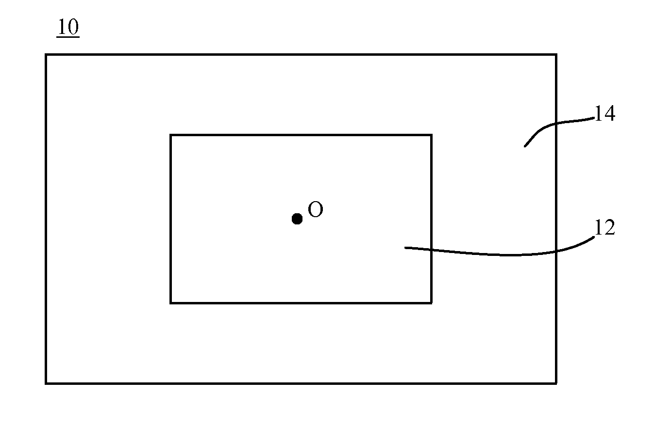
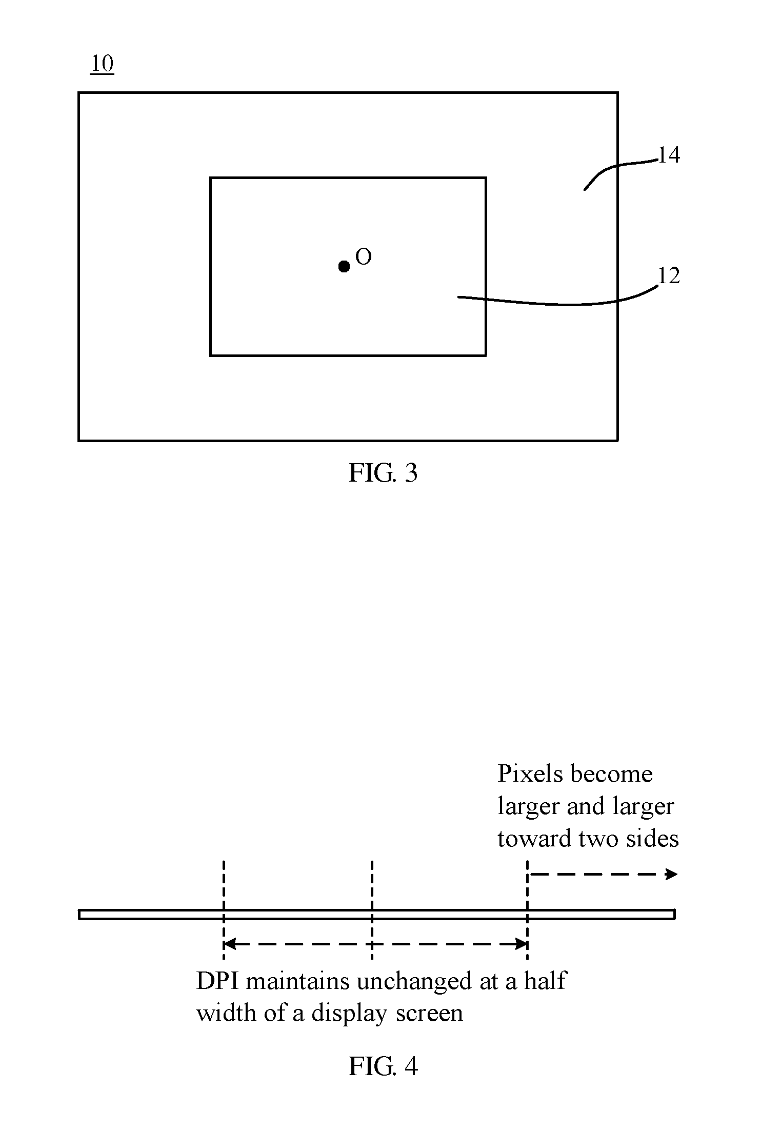
The present invention aims to provide a display panel that solves the problem of circuit instability caused by disposing a large number of pixels on a high-resolution display panel. Additionally, it also reduces the number of pixels required while keeping the visual perception of human eyes unaffected. The invention achieves this by utilizing the characteristic of human eyes that allows for a higher visual perception in the peripheral region compared to the central region. This results in reduced pixel distribution density in the peripheral region while maintaining the same pixel distribution density in the central region. This, in turn, helps to solve the circuit instability issue and reduce the number of pixels necessary for a high-resolution display.

Problems solved by technology

When the resolution of display panel becomes higher, the image performance becomes more delicate and more like a real object, in addition, the image quality of the display panel is increased as well.
However, it has to shrink the pixel size of the display panel to prevent the user from seeing coarse images.
However, it is inevitable to increase the number of pixels in the display panel and the number of thin-film transistors (TFTs) becomes large as well when the pixel size is reduced for improving the resolution of the display panel.
Also, this may aggravate a RC delay occurred on gate electrodes and thus affect signal transmission.

Method used


Image

  • Display panel having non-uniform pixel distribution density
  • Display panel having non-uniform pixel distribution density
  • Display panel having non-uniform pixel distribution density

Examples


Embodiment Construction

[0028]The following descriptions for the respective embodiments are specific embodiments capable of being implemented for illustrations of the present invention with referring to appended figures. In the descriptions of the present invention, spatially relative terms, such as “upper”, “lower”, “front”, “back”, “left”, “right”, “top”, “bottom”, “horizontal”, “vertical”, and the like, may be used herein for ease of description as illustrated in the figures. Therefore, it will be understood that the spatially relative terms are intended to illustrate for understanding the present invention, but not to limit the present invention.

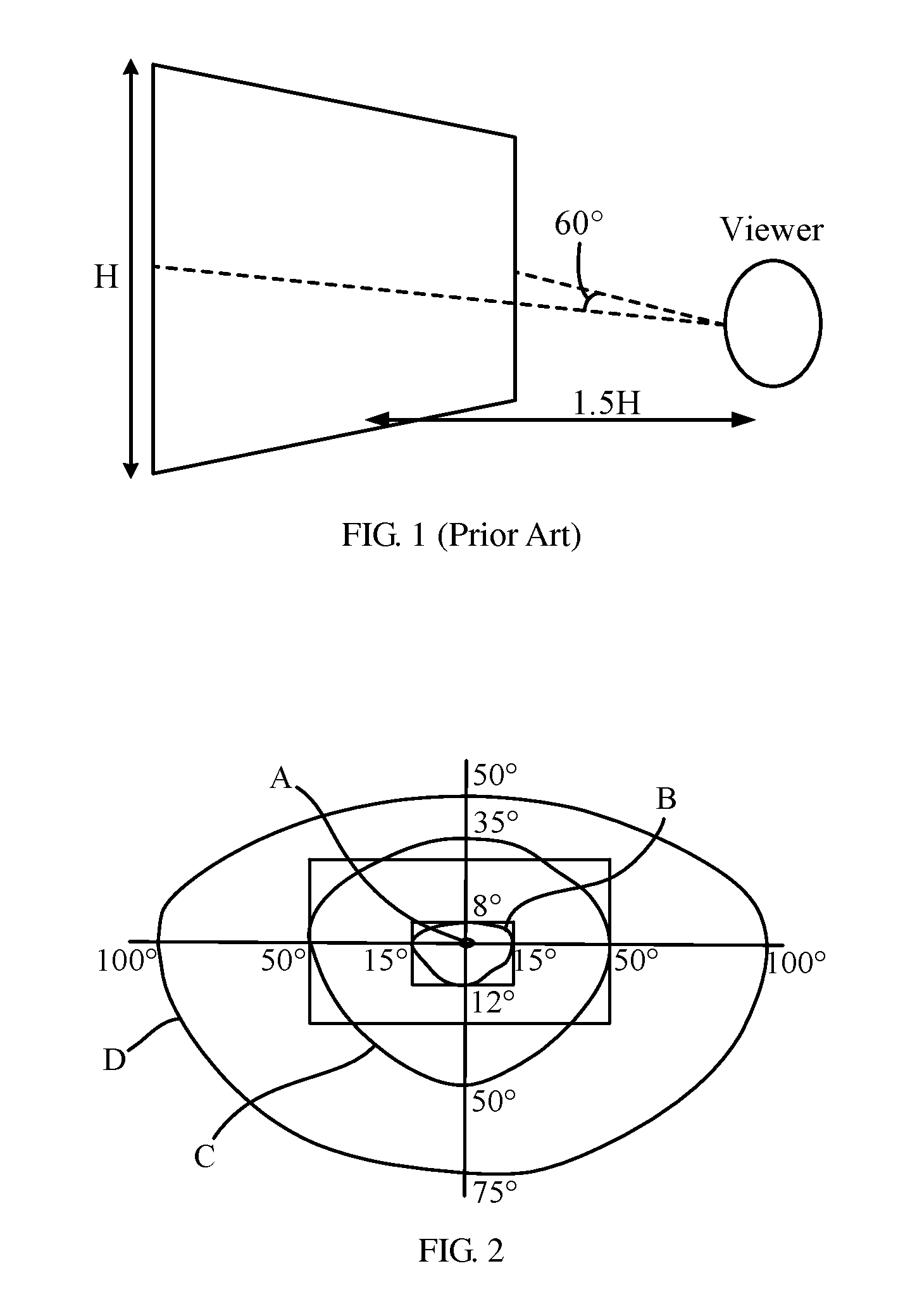
[0029]Referring to FIG. 2, the sensibility of human eyes differs from different fields of view. In general, according to different visual perception, it can be classified into a resoluble field of view (A), an effective field of view (B), an inductive field of view (C), and an auxiliary field of view (D), sequentially.

[0030]Based on different visual perception ...


PUM


Abstract

A display panel is disclosed. The display panel is divided into a central region and a peripheral region. The central region is located at a central position of the display panel. The central region is extended outward from the central position and occupies a predetermined area. The peripheral region surrounds the central region. It is noted that distribution density of the pixels located in the central region is greater than that of the pixels located in the peripheral region. The present invention can solve the problem of circuit instability caused by disposing a large number of pixels on a high-resolution display panel.

Description

TECHNICAL FIELD OF THE INVENTION[0001]The present invention relates to a display panel, and more particularly, to a display panel having non-uniform pixel distribution density.BACKGROUND OF THE INVENTION[0002]Liquid crystal display (LCD) panels become a mainstream of television (TV) panels. To satisfy the needs of human visual perception, the display panels are gradually improved. For example, the response time of liquid crystal molecules is reduced for achieving a better dynamic video effect; the occurrence of dark-state light leakage of the display panel is minimized for improving contrast; and the problems of color cast and contrast have to be solved for improving the image quality of wide viewing angle display products.[0003]Recently, the resolution of TV panel is significantly enhanced. There are three versions: high definition (HD, 1366×768) at early times, full high definition (FHD, 1920×1080), and 4K resolution (4K×2K) that has been developed currently. When the resolution o...

Claims


Application Information

Patent Timeline
Patent Type & Authority Applications(United States)
IPC IPC(8): G06T17/00G09G3/36
CPCG06T17/00G09G3/36G02F1/1333G09F9/302G02F1/133391G02F1/133388
Inventor HUO, HUNG-LUNG
Owner TCL CHINA STAR OPTOELECTRONICS TECH CO LTD
Learn More