Vehicular Power Conversion Apparatus

Inactive Publication Date: 2013-10-24
HITACHI AUTOMOTIVE SYST LTD
View PDF9 Cites 39 Cited by
  • Summary
  • Abstract
  • Description
  • Claims
  • Application Information

AI Technical Summary

Benefits of technology

[0014]According to the present invention, it is possible to reduce influe

Problems solved by technology

This poses a problem in that the electric components may be influenced by heat resulting from either heat transfer amo

Method used


Image

  • Vehicular Power Conversion Apparatus
  • Vehicular Power Conversion Apparatus
  • Vehicular Power Conversion Apparatus

Examples


Embodiment Construction

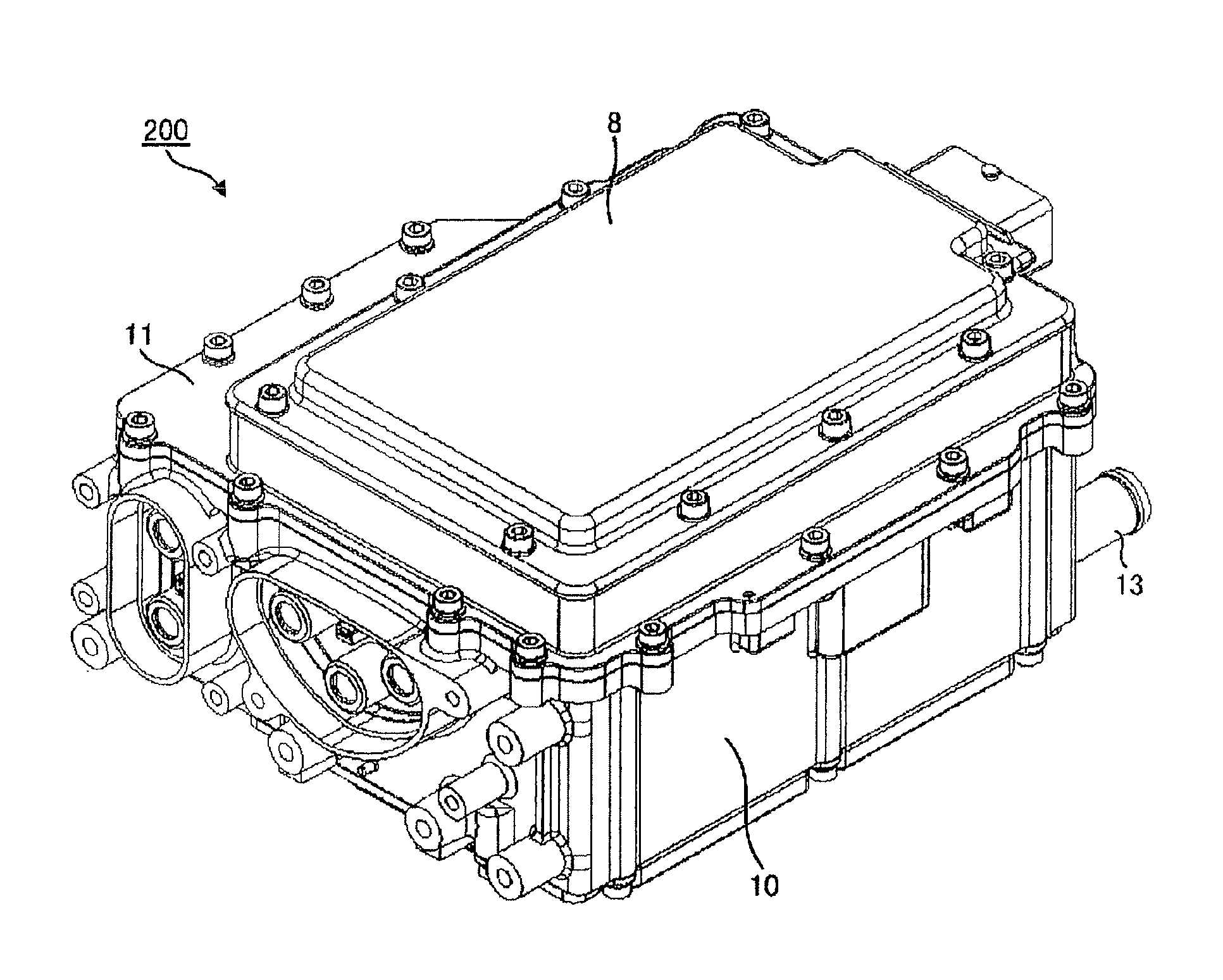
[0040]A power conversion apparatus described in the following embodiments to which the present invention is applied, as well as a system using the apparatus, solves various problems that are needed to be solved for commercial production. One of the various problems solved by these embodiments is a problem regarding influence of heat resulting from compactness of the power conversion apparatus, which is described above in the section of Technical Problem. Furthermore, various problems other than the above-described problems and effects are solved, making it possible to achieve various effects.

[0041]For example, in connection with a problem of improving resistance to vibration, not only the configuration described above in the section of Technical Problem, but other configurations can also solve the problem.

[0042]In other words, in connection with the problem of improving resistance to vibration and relevant effects, configurations other than the above-described configuration solve, t...


PUM


Abstract

A first power semiconductor module and a second power semiconductor module are fixed in parallel to a first channel along a flow direction of a cooling refrigerant flowing through the first channel, a third power semiconductor module is fixed to a second channel such that the first power semiconductor module and the third power semiconductor module face each other via a capacitor circuit unit, and an electric circuit element electrically connected in series or in parallel with regard to the capacitor circuit unit and a DC terminal is arranged in such a position that the second power semiconductor module and the electric circuit element face each other via the capacitor circuit unit.

Description

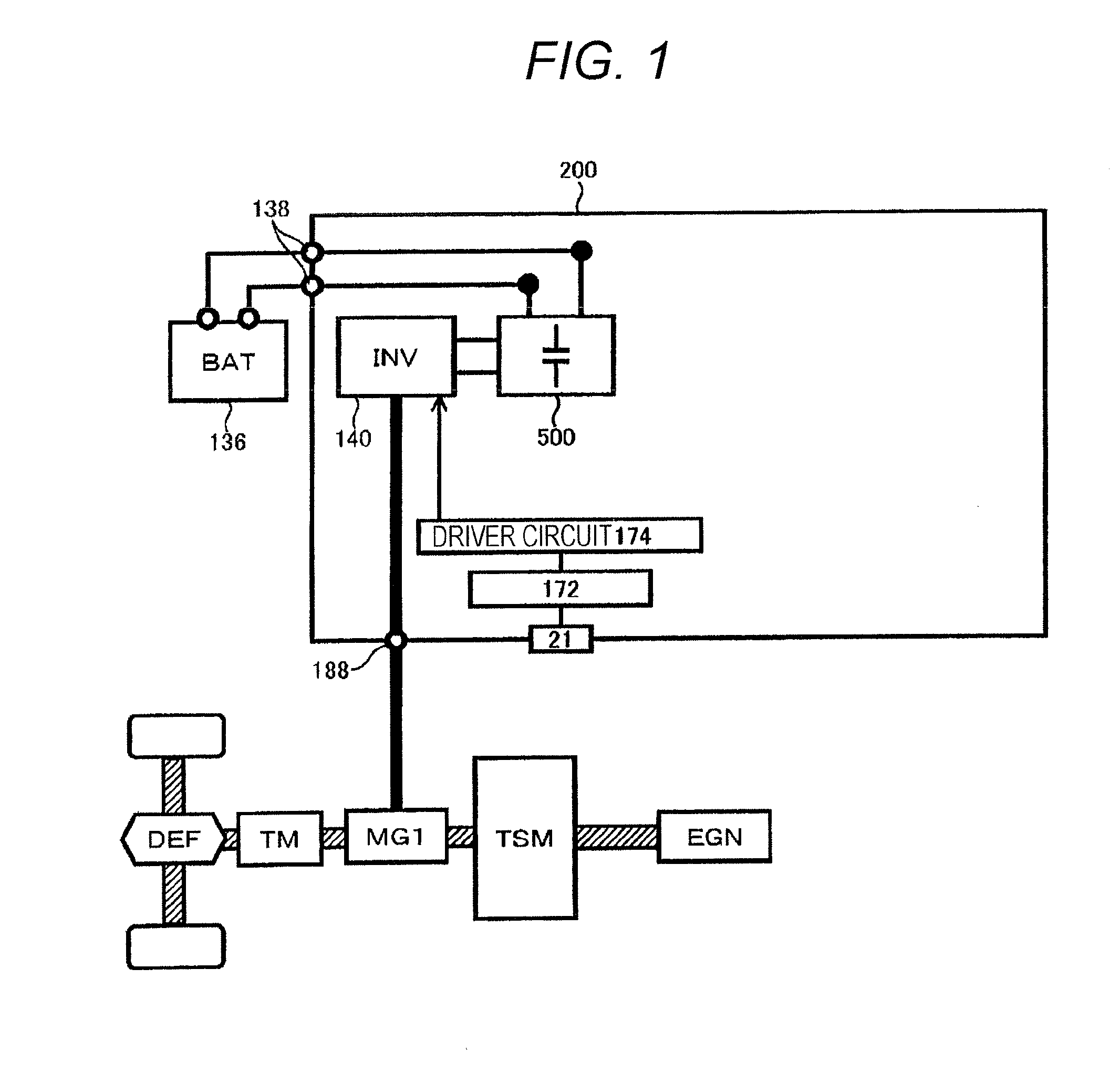
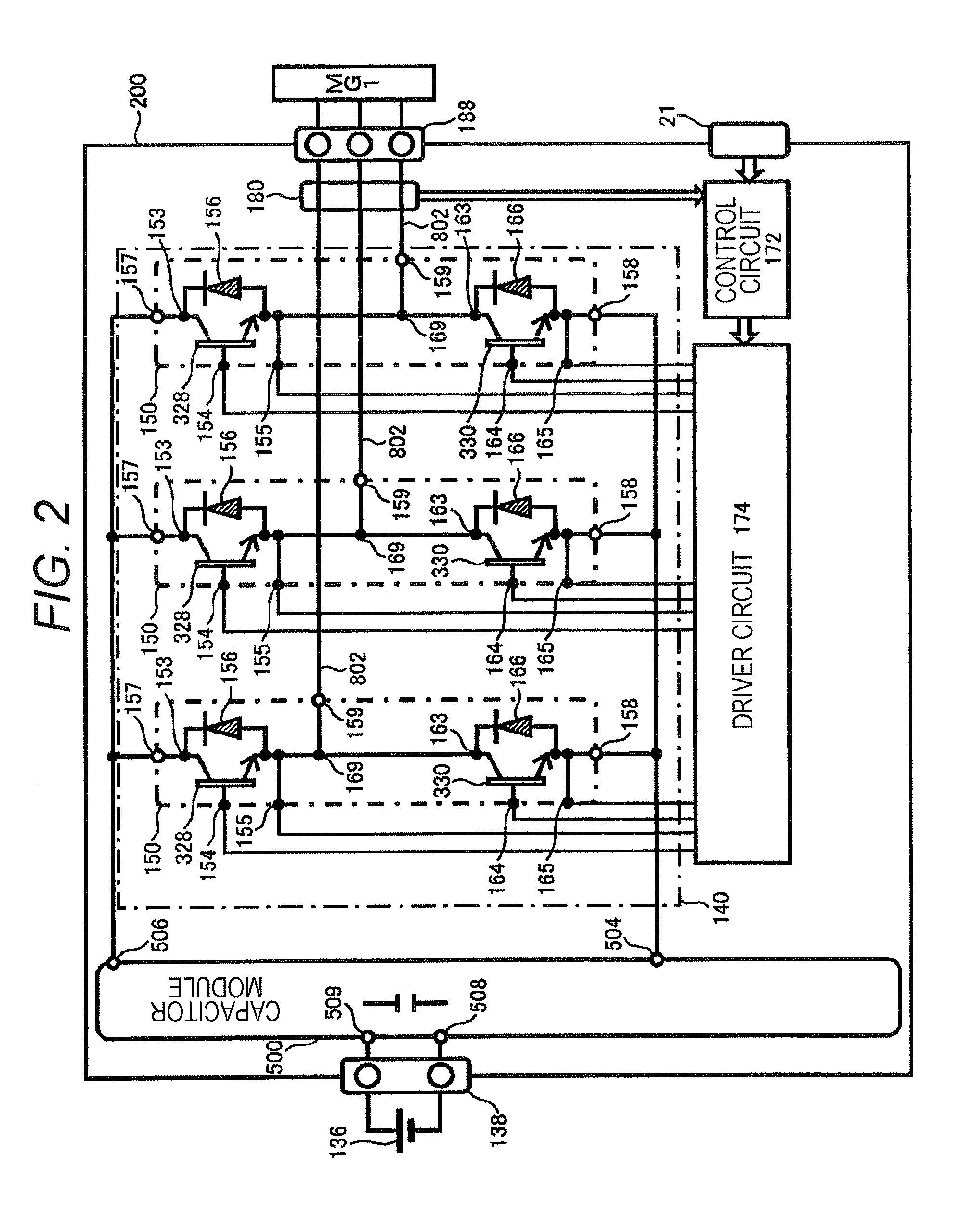
TECHNICAL FIELD[0001]The present invention relates to a power conversion apparatus used to convert DC power to AC power or to convert AC power to DC power.BACKGROUND ART[0002]In general, a power conversion apparatus includes a smoothing capacitor module configured to receive DC power from a DC power source, an inverter circuit configured to receive DC power from the capacitor module and generate AC power, and a control circuit for controlling the inverter circuit. The AC power is supplied to a motor, for example, and the motor generates rotation torque according to the supplied AC power. The motor generally has a function as a generator and, when supplied with mechanical energy from the outside, the motor generates AC power based on the supplied mechanical energy. The power conversion apparatus also has a function for converting AC power to DC power in many cases, and AC power generated by the motor is converted into DC power. Conversion from DC power to AC power or conversion from ...

Claims


Application Information

Patent Timeline
IPC IPC(8): H01L23/473B60L50/16
CPCH01L23/473B60K6/28B60K6/48B60L15/007B60Y2400/112B60Y2400/114H02M7/003H01L2924/0002B60L2240/525H01L25/072B60L2270/145B60L2270/147B60L3/003Y02T10/62Y02T10/64H01L2924/00
Inventor NISHIKIMI, FUSANORIKUMAGAI, MASATOISHII, AKIRA
Owner HITACHI AUTOMOTIVE SYST LTD
Why Eureka
Try Eureka