
Systems and apparatuses for providing conversion from a first optical connector to multiple second optical connectors

a technology of optical connectors and conversion systems, applied in the field of communication equipment, can solve the problems of insufficient surface area to accommodate a plurality of 10 g interfaces, configuration can suffer from fiber length mismatch issues, and the number of optical devices can be shortened, so as to achieve the effect of reducing costs

Inactive Publication Date: 2013-10-24
TELLABS OPERATIONS
View PDF5 Cites 16 Cited by
  • Summary
  • Abstract
  • Description
  • Claims
  • Application Information

AI Technical Summary

Benefits of technology

The patent text describes a system that eliminates the need for small form-factor pluggable (SFP+) cages and associated crosspoints, reducing costs and allowing support for both transponder and muxponder applications. This results in more efficient and cost-effective network solutions.

Problems solved by technology

Generally, pluggable optical devices of the QSFP+ type support a 40 G interface, but do not have sufficient surface area to be able to accommodate a plurality of 10 G interfaces, owing to the amount of area that would be required for the associated LC optical connectors and patch panels to accommodate such interfaces.
Also, even if a break-out cable (which has been used in the prior art to support 10 G client equipment) were to be connected to the 40 G interface of a QSFP+, and 10 G fibers of the break-out cable were to be connected to 10 G client equipment externally from the QSFP+, such a configuration can suffer from fiber length mis-match issues.

Method used


Image

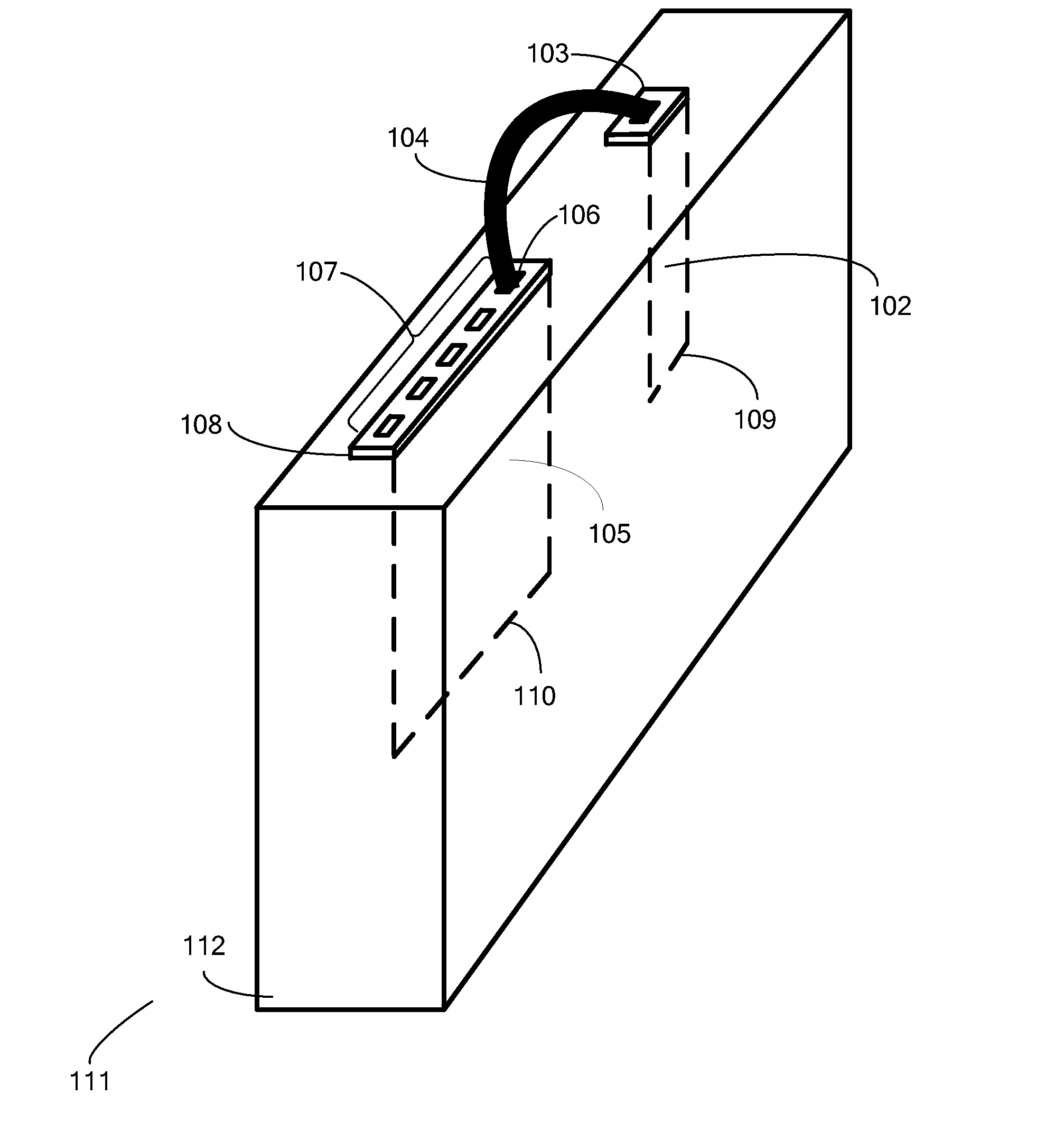
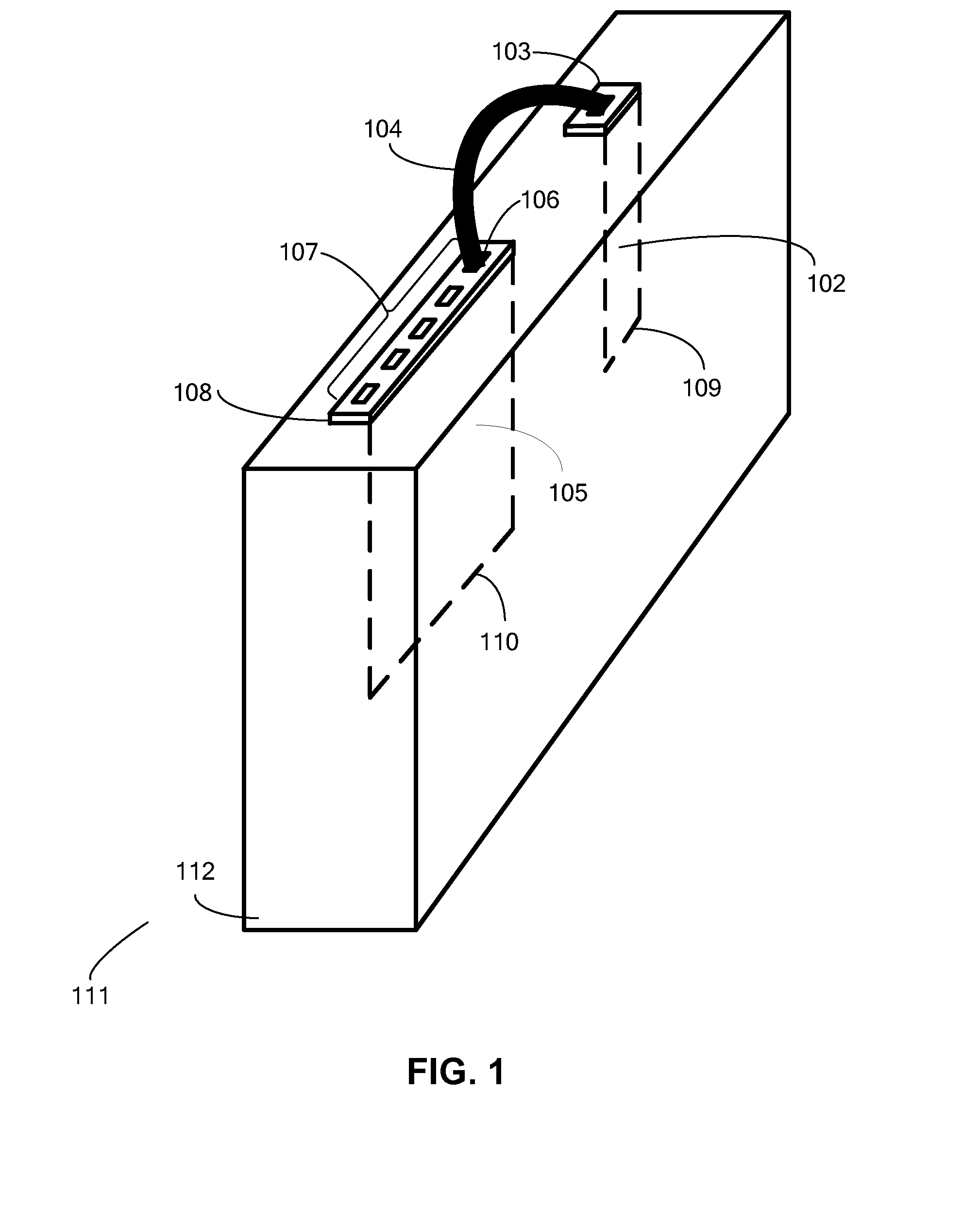
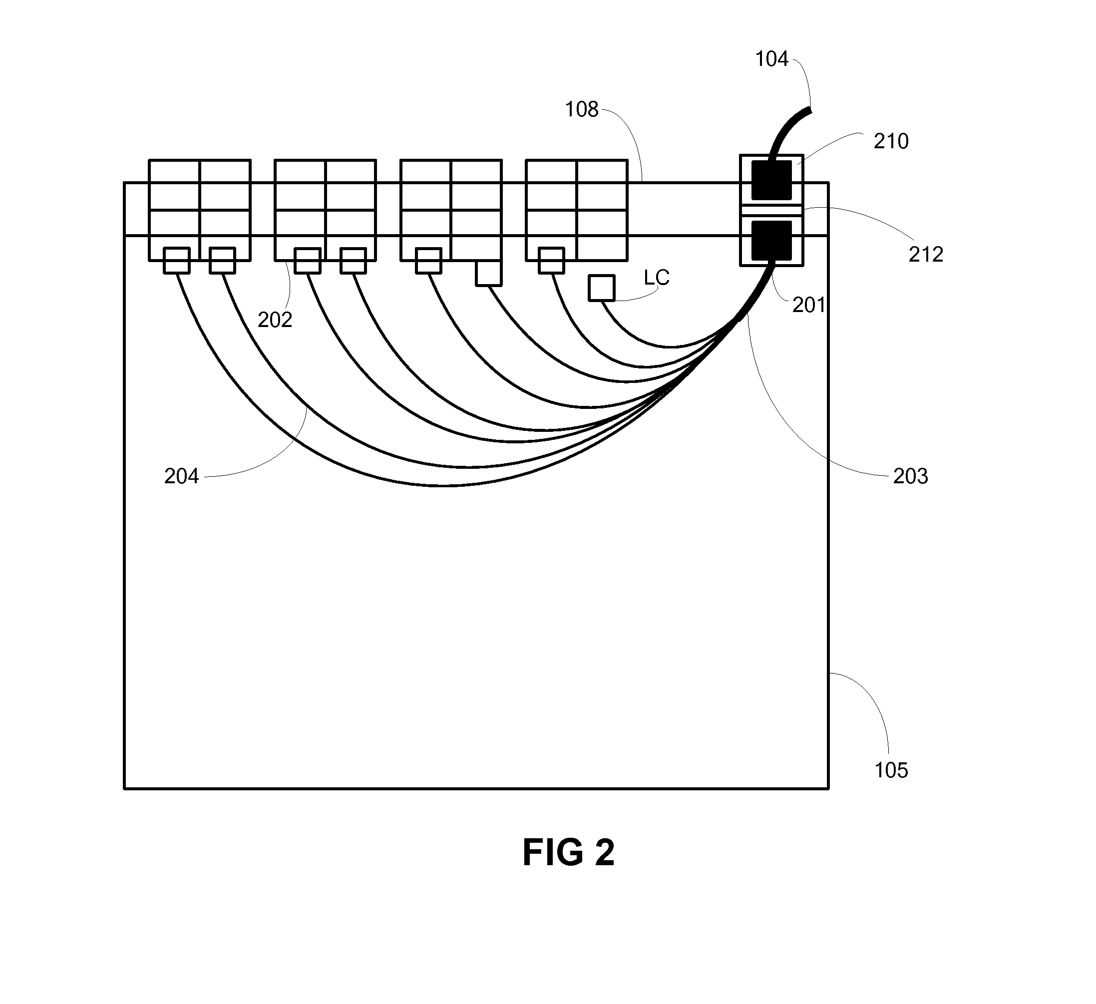
  • Systems and apparatuses for providing conversion from a first optical connector to multiple second optical connectors
  • Systems and apparatuses for providing conversion from a first optical connector to multiple second optical connectors
  • Systems and apparatuses for providing conversion from a first optical connector to multiple second optical connectors

Examples


Embodiment Construction

[0026]The present application presents several novel and inventive approaches for combining the capabilities of multiple pluggable optical devices, such as optical transceivers, to enable at least one of them to accommodate at least one functional capability that it would not otherwise be able to accommodate.

[0027]As described above, generally it is difficult, if not impossible, to make pluggable optical devices of the small form-factor pluggable plus (QSFP+) type accommodate a plurality of 10 G interfaces, owing to the amount of space that would be required for the associated connectors. Thus, such QSFP+ devices generally do not operate with direct 10 G-capable connections that would be used to connect to, for example, external client equipment. However, according to an example aspect herein, a configuration is provided that enables a pluggable optical device, such as a QSFP+ optical device, to operate with such a capability.

[0028]By example only, one example embodiment herein enab...


PUM


Abstract

An optical connector system having a first optical connector, a plurality of second optical connectors, and a mounting system hosting the first optical connector and the second optical connectors. The mounting system can be formed integrally with at least one pluggable optical device. The system also has a mechanism arranged to connect the first optical connector to the second optical connectors. The system also includes at least one further pluggable optical device having at least one optical interface optically coupled to the first optical connector of the at least one pluggable optical device. In one example, the pluggable optical device is a CFP device, and the further pluggable optical device is a QSFP+. With this configuration, the QSFP+ can accommodate at least one of a 40 G and 10 G interface capability. Also provided is a connector system and an apparatus (e.g., pluggable optical device) that enable such a capability.

Description

BACKGROUND[0001]1. Field[0002]Example aspects described herein relate generally to communications equipment, and more specifically to systems and apparatuses that enable a pluggable optical device to accommodate multiple communication interface types.[0003]2. Description Of The Related Art[0004]In today's high-technology world, data needs to be transmitted over high-speed computer networks. Optical fibers serve as good network data carriers because, in addition to being flexible and enabling signals to travel with little attenuation, they can each transmit data at a rate of at least ten gigabits (10 G) per second, often at least 40 G per second.[0005]Signals that are communicated using optical fibers are often sent and received by pluggable optical devices. One known type of pluggable optical device is a C form-factor pluggable (CFP), which is multi-source and hot-pluggable. Another known type of pluggable optical device is a quad small form-factor pluggable plus (QSFP+), which is s...

Claims


Application Information

Patent Timeline
Patent Type & Authority Applications(United States)
IPC IPC(8): G02B6/38
CPCG02B6/4286G02B6/3897G02B6/4471
Inventor BODUCH, MARK E.WANG, YAJUNHUBER, THOMAS J.
Owner TELLABS OPERATIONS
Learn More