High-Pressure Fuel Pump
a fuel pump and high-pressure technology, applied in the direction of liquid fuel engines, piston pumps, positive displacement liquid engines, etc., can solve the problems of reducing compression efficiency and large volume of pressurizing chambers, and achieve high energy efficiency, high compression efficiency, and high energy efficiency without increasing the volume of compression chambers
- Summary
- Abstract
- Description
- Claims
- Application Information
AI Technical Summary
Benefits of technology
Problems solved by technology
Method used
Image

Examples
first embodiment
[0019]The construction and operation of a fuel feeding system related to this embodiment will be described below with reference to FIG. 4. FIG. 4 is a general outline view of the system.
[0020]The portion enclosed with a broken line represents a pump body 1 of a high-pressure fuel pump. An arrangement and parts inside the enclosing broken line are integrally installed in the pump body 1.
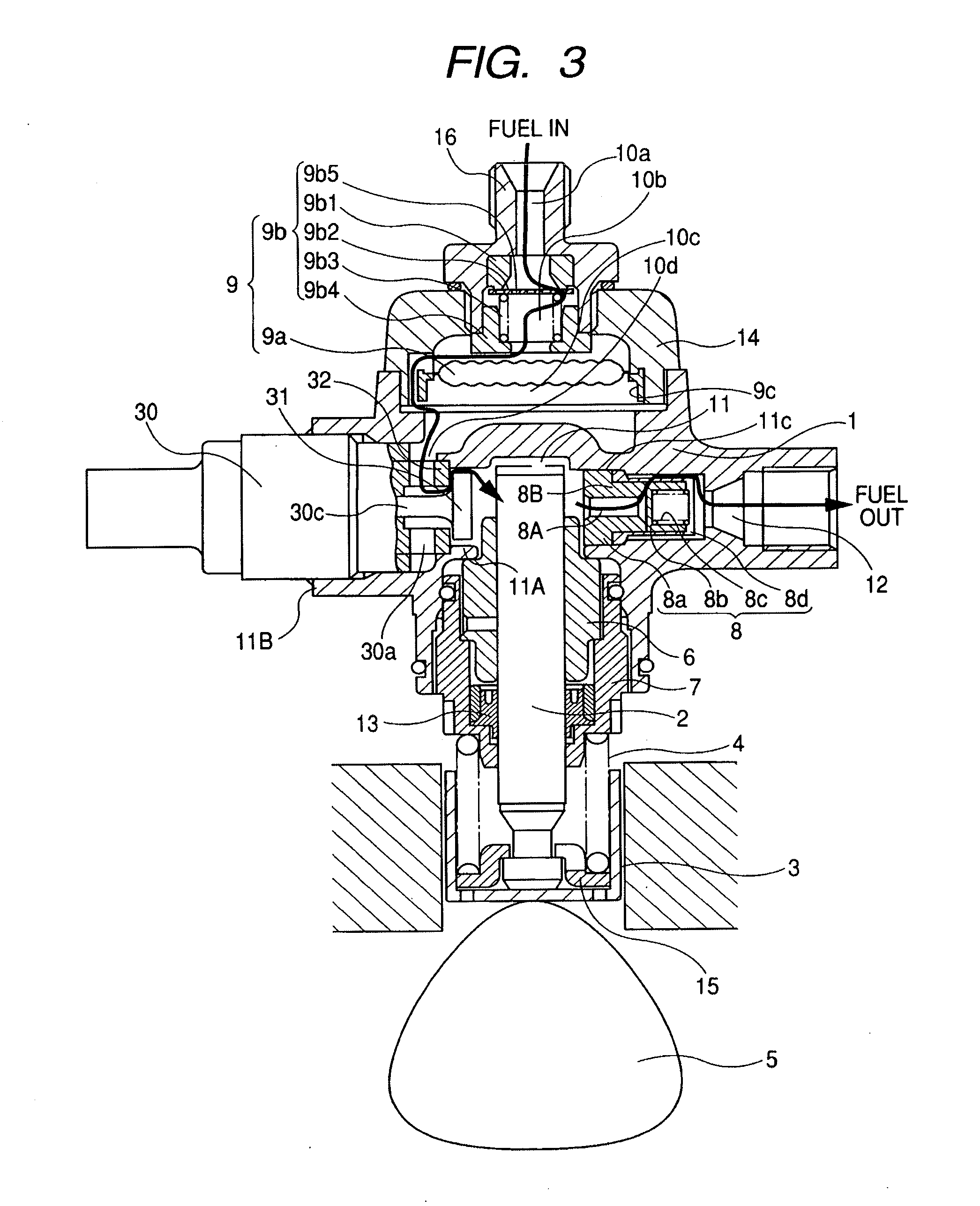
[0021]Fuel in a fuel tank 20 is pumped up by a feed pump 21 and is fed to an inlet joint 10a in the pump body 1 through a suction pipe 28. At this time, the pressure of the fuel to be fed to the pump body 1 is regulated to a constant pressure by a pressure regulator 22.
[0022]The fuel having passed through the inlet joint 10a then passes through a pressure pulsation damping device 9 and an inlet passage 10d, and the fuel reaches pre-inlet port 30a of a solenoid-controlled inlet valve 30. The inlet valve 30 constitutes a capacity variable mechanism for the high-pressure fuel pump. As to the pressure pul...
second embodiment
[0102]A second embodiment of the present invention will be described below with reference to FIGS. 6 and 7.
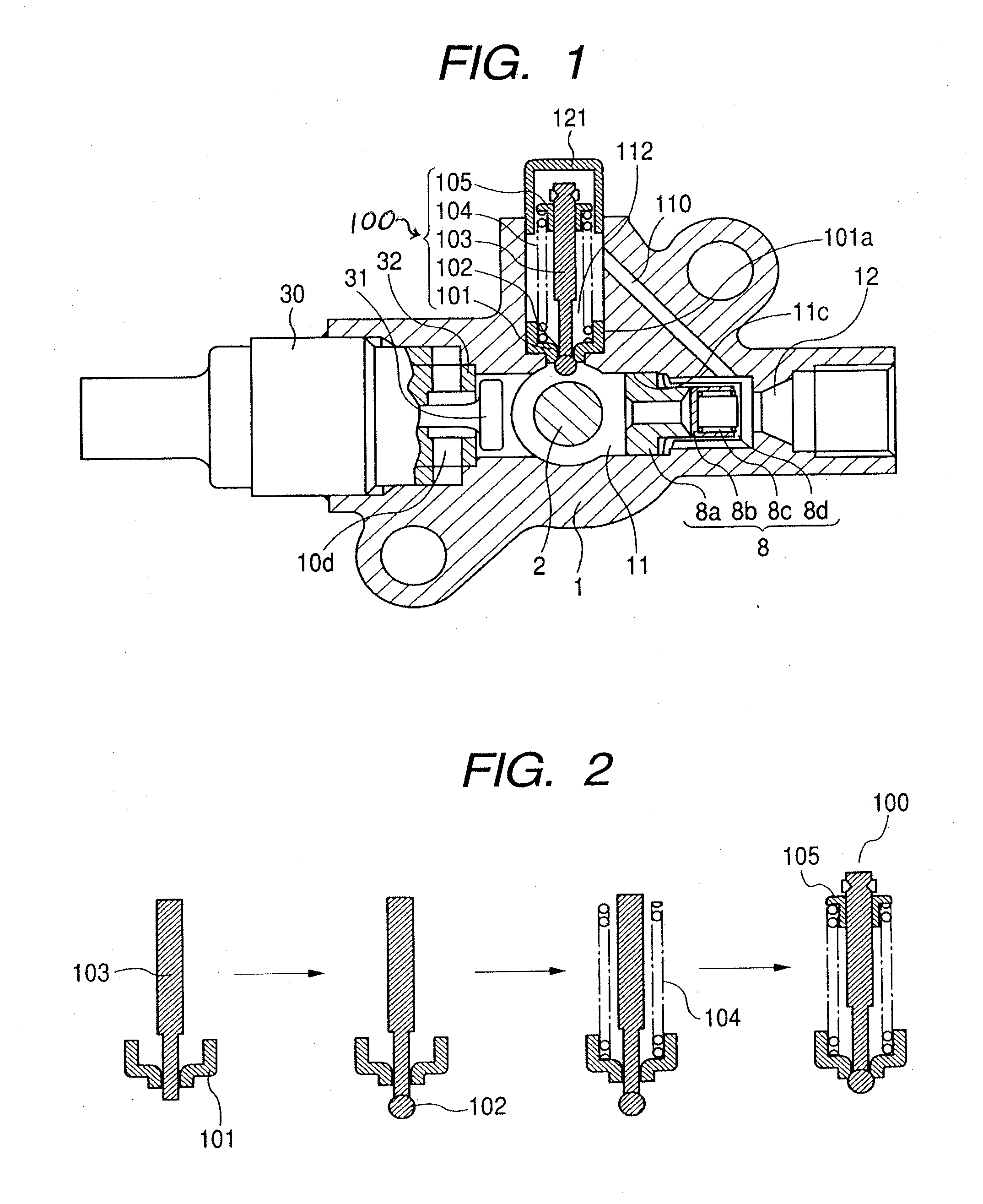
[0103]In the example shown in FIG. 6, a unitized relief valve device 100 is mounted on top of the pressurizing chamber 11. In this example, a holder 111 for the relief valve device is fixed integrally to a relief valve seat 101 by welding 111a. The holder 111 is provided with an aperture 111b for communicating to a relief passage 110. Other members identified by the same reference numerals as in the first embodiment represent the same functional members as in the first embodiment.
[0104]In this embodiment, an aperture 11F is formed in the top of the pressurizing chamber 11. The aperture 11F is closed with the relief valve seat 101 and the relief valve 102. Only the relief valve 102 among all members of the relief valve device is disposed on the pressurizing chamber 11-side. When the relief valve 102 opens, the relief chamber 112 and the aperture 11F communicate to each other thr...
third embodiment
[0106]A third embodiment of the present invention will be described below with reference to FIG. 8.
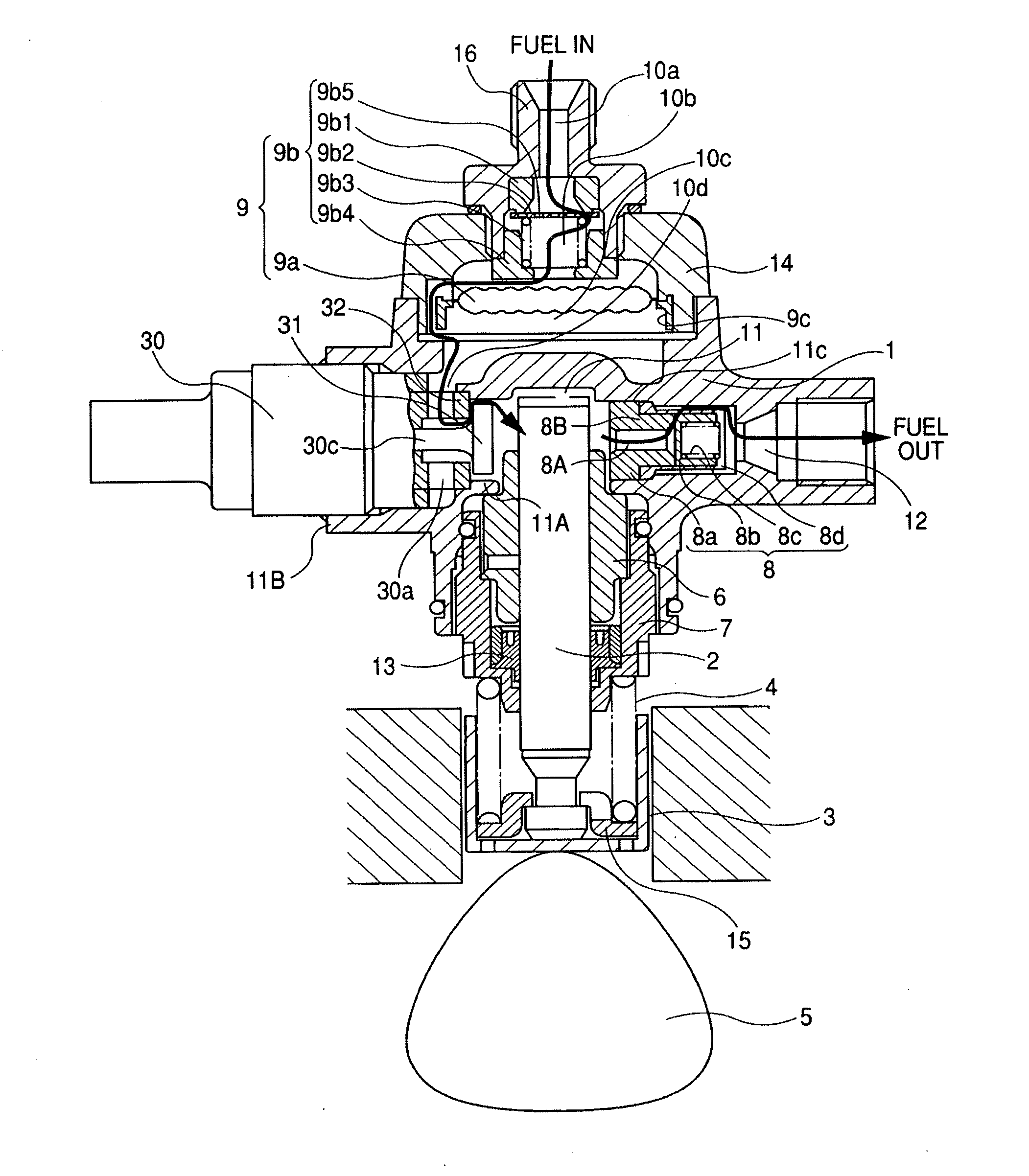
[0107]In the embodiment illustrated in FIG. 8 the fuel outlet port 12 and the relief passage 110 are disposed in a triangular form and this point is the same as in the embodiment illustrated in FIG. 1.
[0108]In the embodiment illustrated in FIG. 1, because of the type wherein the outlet valve device 8 is mounted from the pressurizing chamber side, the inlet-side hole 11A and the outlet-side hole 11C in the pressurizing chamber are disposed on the same axis.
[0109]In such a type as the embodiment illustrated in FIG. 8 wherein the outlet valve device 8 is mounted into the outlet-side hole 11C from the outside of the pump body 1, it is possible to construct the pump so that the solenoid-controlled inlet valve 30 and the relief valve device 100 are disposed on the same axis.
PUM
 Abstract
Description
Claims
Application Information
 - R&D
- Intellectual Property
- Life Sciences
- Materials
- Tech Scout
- Unparalleled Data Quality
- Higher Quality Content
- 60% Fewer Hallucinations
Browse by: Latest US Patents, China's latest patents, Technical Efficacy Thesaurus, Application Domain, Technology Topic, Popular Technical Reports.
© 2025 PatSnap. All rights reserved.Legal|Privacy policy|Modern Slavery Act Transparency Statement|Sitemap|About US| Contact US: help@patsnap.com